Back to Contents Page
Dell™ PowerEdge™ 1750 Systems
Installation and Troubleshooting Guide
To perform certain procedures in this document, you must remove the system cover and work inside the system. While working inside the system, do not attempt to service the system except as explained in this guide and elsewhere in your system documentation.

|
Always follow the instructions closely, and ensure that you review all information in "Safety Instructions" in the System Information Guide. |
|
|
CAUTION: Only trained service technicians are authorized to remove the system cover and access any of the components inside the system. See your System Information Guide for complete information about safety precautions, working inside the computer, and protecting against electrostatic discharge. |
This section provides troubleshooting procedures for external devices attached to the system, such as the monitor, keyboard, or mouse. Before you perform any of the procedures, see "Troubleshooting External Connections."
Look and listen during the system's start-up routine for the indications described in Table 5-1.
Table 5-1. Start-Up Routine Indications
Loose or improperly connected cables are the most likely source of problems for the system, monitor, and other peripherals (such as a printer, keyboard, mouse, or other external device). Ensure that all external cables are securely attached to the external connectors on your system. See Figure 2-4 for the back-panel connectors on your system; see Figure 2-2 for the front-panel connectors.
- Monitor is not working properly.
- Video memory is faulty.
- Check the system and power connections to the monitor.
- Determine whether the system has monitors attached to both the front and rear video
connectors.
The system supports only one monitor attached to either the front or rear video connector. When a monitor is connected to the front panel, the back-panel video and PS/2 keyboard and mouse connectors are disabled.
If two monitors are attached to the system, disconnect one monitor. If the problem is not resolved, continue to the next step.
- Check the system and power connections to the monitor.
- Run the appropriate online diagnostic test. See "Using Server Administrator
Diagnostics" in "Running System Diagnostics."
If the tests run successfully, the problem is not related to video hardware. See "Finding Software Solutions."
If the tests fail, see "Getting Help."
- System message indicates a problem with the keyboard.
- Keyboard is not functioning properly.
- Ensure that the keyboard is properly connected to the system.
- Run the appropriate online diagnostic test. See "Using Server Administrator
Diagnostics" in "Running System Diagnostics."
If the test fails, continue to the next step.
- Press each key on the keyboard, and examine the keyboard, cable, and cable connector
for signs of damage, including bent pins.
If the keyboard is not damaged, go to step 5.
If the keyboard is damaged, continue to the next step.
- Swap the faulty keyboard with a working keyboard.
If the problem is resolved, replace the faulty keyboard. See "Getting Help."
- Run the keyboard test in the system diagnostics. See "Running the System
Diagnostics."
If the test fails, see "Getting Help."
- System message indicates a problem with the mouse.
- Mouse is not functioning properly.
- Run the appropriate online diagnostic test. See "Using Server Administrator
Diagnostics" in "Running System Diagnostics."
If the test fails, continue to the next step.
- Examine the mouse and its cable for signs of damage.
If the mouse is not damaged, go to step 4.
If the mouse is damaged, continue to the next step.
- Swap the faulty mouse with a working mouse.
If the problem is resolved, replace the faulty mouse. See "Getting Help."
- Enter the System Setup program and ensure that the mouse controller is enabled. See
"Using the System Setup Program" in your User's Guide.
If the problem is not resolved, continue to the next step.
- Run the pointing devices test in the system diagnostics. See "Running the System
Diagnostics."
If the test fails, see "Getting Help."
- Error message indicates a problem with a serial port.
- Device connected to a serial port is not operating properly.
- Enter the System Setup program and ensure that the serial port(s) are enabled. See
"Using the System Setup Program" in the User's Guide.
- If the problem is confined to a particular application, see the application
documentation for specific port configuration requirements that the program may
require.
- Run the appropriate online diagnostic test. See "Running the System Diagnostics" in
"Running System Diagnostics."
If the tests run successfully but the problem persists, see "Troubleshooting a Serial I/O Device."
- Device connected to the serial port is not operating properly.
- Turn off the system and any peripheral devices connected to the serial port.
- Swap the serial interface cable with a working cable, and turn on the system and the
serial device.
If the problem is resolved, replace the interface cable. See "Getting Help."
- Turn off the system and the serial device, and swap the device with a comparable
device.
- Turn on the system and the serial device.
If the problem is resolved, replace the serial device. See "Getting Help."
If the problem persists, see "Getting Help."
- System message indicates a problem with a USB device.
- Device connected to a USB port is not operating properly.
- Enter the System Setup program, and ensure that the USB ports are enabled. See
"Using the System Setup Program" in your User's Guide.
- Turn off the system and any USB devices.
- Disconnect the USB devices, and connect the malfunctioning device to the other USB
connector.
- Turn on the system and the reconnected device.
If the problem is resolved, the USB connector might be defective. See "Getting Help."
- If possible, swap the interface cable with a working cable.
If the problem is resolved, replace the interface cable. See "Getting Help."
- Turn off the system and the USB device, and swap the device with a comparable
device.
- Turn on the system and the USB device.
If the problem is resolved, replace the USB device. See "Getting Help."
If the problem persists, see "Getting Help."
- NIC cannot communicate with network.
- Run the appropriate online diagnostic test. See "Using Server Administrator
Diagnostics" in "Running System Diagnostics."
If the tests fail, continue to the next step.
- Check the appropriate indicator on the NIC connector. See Table 2-2 in "Indicators,
Messages, and Codes."
- If the link indicator does not light, check all cable connections.
- If the activity indicator does not light, the network driver files might be damaged or missing.
Remove and reinstall the drivers if applicable. See the NIC's documentation.
- Change the autonegotiation setting, if possible.
- Use another connector on the switch or hub.
If you are using a NIC card instead of an integrated NIC, see the documentation for the NIC card.
- Ensure that the appropriate drivers are installed and the protocols are bound. See the
NIC's documentation.
- Enter the System Setup program and confirm that the NICs are enabled. See "Using
the System Setup Program" in your User's Guide.
- Ensure that the NICs, hubs, and switches on the network are all set to the same data
transmission speed. See the network equipment documentation.
- Ensure that all network cables are of the proper type and do not exceed the maximum
length. See "Network Cable Requirements" in your User's Guide.
Systems management software monitors critical system voltages and temperatures, fans, and hard drives in the system. Alert messages appear in the Alert Log window. For information about the Alert Log window, see the systems management software documentation.
In Figure 5-1, the system covers are open and the bezel is removed to provide an interior view of the system.
Figure 5-1. Inside the System
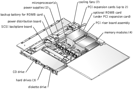
The system board can accommodate one or two microprocessors. The PCI riser board assembly accommodates up to two PCI expansion cards. Up to four memory modules may be installed on the system board.
The hard-drive bays provide space for up to three 1-inch SCSI hard drives. SCSI hard drives are connected to a SCSI controller on the system board through the SCSI backplane board.
The peripheral bays provide space for an optional 3.5-inch diskette drive and a CD drive.
The power distribution board (PDB) provides hot-plug logic and power distribution for the system. Two hot-pluggable, redundant power supplies provide power to the system board and internal peripherals.
During an installation or troubleshooting procedure, you may be required to change a jumper. For information about the system board jumpers, see "Jumpers and Connectors."
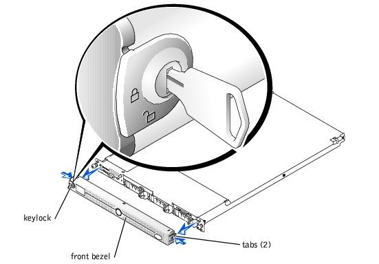
The front bezel has system status indicators. A lock on the bezel restricts access to the power button, diskette drive, CD drive, hard drive(s), and the interior of the system.
- To remove the bezel, use the system key to unlock the keylock on the bezel, press the tab at each end of the bezel, and then pull the bezel away from the system. See Figure 5-2.
- To replace the front bezel, fit the tabs on the bezel into the corresponding slots in the front panel and lock the keylock.
Figure 5-2. Removing and Replacing the Optional Front Bezel
Two covers on the top of the system provide access to the system board and other internal components.
To open the system covers, perform the following steps:
- Observe the precautions in "Safety First—For You and Your System." Also observe the
safety instructions in the System Information Guide.
- Slide the system out of the rack.
- If the front bezel is installed, remove the front bezel. See "Removing and Replacing
the Optional Front Bezel."
- If the optional security screw is installed on the system cover (see Figure 5-3), remove
it now.
Figure 5-3. Opening the System Covers
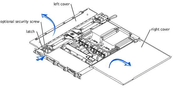
- Press the latch on the system front panel and lift the left cover.
- Lift the right cover.
When closing the covers, close the right (larger) cover first and then close the left cover. Press firmly on the left cover to snap the securing latch into place.
- Liquid spilled on the system.
- Excessive humidity.
|
|
CAUTION: Only trained service technicians are authorized to remove the system cover and access any of the components inside the system. See your System Information Guide for complete information about safety precautions, working inside the computer, and protecting against electrostatic discharge. |
- Turn off the system and attached peripherals, and disconnect the system from the
electrical outlet.
- Open the system. See "Opening the System Covers."
- Remove all expansion cards installed in the system. See "Removing an Expansion
Card" in "Installing System Options."
- Let the system dry thoroughly for at least 24 hours.
- Close the system. See "Closing the System Covers."
- Reconnect the system to the electrical outlet, and turn on the system and attached
peripherals.
If the system does not start properly, see "Getting Help."
- If the system starts properly, shut down the system and reinstall all of the expansion
cards that you removed. See "Installing an Expansion Card" in "Installing System
Options."
- Run the system board tests in the system diagnostics to confirm that the system is
working properly. See "Running the System Diagnostics."
If the tests fail, see "Getting Help."
- System was dropped or damaged.
|
|
CAUTION: Only trained service technicians are authorized to remove the system cover and access any of the components inside the system. See your System Information Guide for complete information about safety precautions, working inside the computer, and protecting against electrostatic discharge. |
- Open the system covers. See "Opening the System Covers."
- Ensure that the following components are properly installed:
- Expansion cards
- Power supplies
- Fans
- Drive-carrier connections to the SCSI backplane board, if applicable
- Ensure that all cables are properly connected.
- Close the cover. See "Closing the System Covers."
- Run the system board tests in the system diagnostics. See "Running the System
Diagnostics."
If the tests fail, see "Getting Help."
- System message indicates a problem with the battery.
- System Setup program loses system configuration information.
- System date and time do not remain current.
- Re-enter the time and date through the System Setup program. See "Using the System
Setup Program" in your User's Guide.
- Turn off the system and disconnect it from the electrical outlet for at least one hour.
- Reconnect the system to the electrical outlet and turn on the system.
- Enter the System Setup program.
If the date and time are not correct in the System Setup program, replace the battery. See "Replacing the System Battery" in "Installing System Options."
If the problem is not resolved by replacing the battery, see "Getting Help."
 |
NOTE: Some software may cause the system time to speed up or slow down. If the
system seems to operate normally except for the time kept in the System Setup
program, the problem may be caused by software rather than by a defective battery.
|
|
NOTE: If the system is turned off for long periods of time (for weeks or months), the
NVRAM may lose its system configuration information. This situation is caused by a
defective battery.
|
- System-status indicators are amber.
- Power-supply fault indicators are amber.
|
|
CAUTION: Only trained service technicians are authorized to remove the system cover and access any of the components inside the system. See your System Information Guide for complete information about safety precautions, working inside the computer, and protecting against electrostatic discharge. |
- Run the appropriate online diagnostics test. See "Using Server Administrator
Diagnostics" in "Running the System Diagnostics."
- Turn off the system and attached peripherals, and disconnect the system from the
electrical outlet.
- Open the system. See "Opening the System Covers."
- Locate the faulty power supply.
The power supply's fault indicator is lit. See Table 2-4 in "Indicators, Messages, and Codes."
 |
NOTICE: The power supplies are hot-pluggable. One power supply must be installed for the
system to operate. The system is in the redundant mode when two power supplies are installed.
Remove and install only one power supply at a time in a system that is powered on.
|
- Ensure that the power supply is properly installed by removing and reinstalling it. See
"Removing and Replacing Power Supplies" in "Installing System Options."
|
NOTE: After installing a power supply, allow several seconds for the system to recognize
the power supply and to determine if it is working properly. The power indicator turns green
to signify that the power supply is functioning properly. See Table 2-4 in "Indicators,
Messages, and Codes."
|
- If the problem is resolved, close the system covers. See "Closing the System Covers."
If the problem persists, remove the faulty power supply. See "Removing a Power Supply" in "Installing System Options."
- Install a new power supply. See "Installing a Power Supply" in "Installing System
Options."
If the problem persists, see "Getting Help."
- Systems management software issues a fan-related error message.
Action
Ensure that none of the following conditions exist:
- Ambient temperature is too high.
- External airflow is obstructed.
- An individual cooling fan has failed. See "Troubleshooting a Fan."
- System-status indicator is amber.
- Systems management software issues a fan-related error message.
- Fan status indicator indicates a problem with the fan.
- Run the appropriate diagnostic test. See "Using Server Administrator Diagnostics" in
"Running System Diagnostics."
|
|
CAUTION: Only trained service technicians are authorized to remove the system cover and access any of the components inside the system. See your System Information Guide for complete information about safety precautions, working inside the computer, and protecting against electrostatic discharge. |
|
|
CAUTION: Redundant cooling is not supported. Replace a failed fan as soon as possible. |
- Open the system. See "Opening the System Covers."
|
|
CAUTION: The cooling fans are hot-pluggable. To maintain proper cooling while the system is on, replace only one fan at a time. |
- Locate the fan indicator that is blinking amber.
|
NOTE: The fan indicators are small LEDs located next to each fan power connector. A
solid green LED means that the fan is operating correctly; a blinking amber LED indicates
a problem.
|
- Ensure that the faulty fan's power cable is firmly attached to the fan power connector.
See "Removing and Replacing System Fans" in "Installing System Options."
|
NOTE: Wait 30 seconds for the system to recognize the fan and determine whether it is
working properly.
|
- If the problem is not resolved, install a new fan. See "Removing and Replacing System
Fans" in "Installing System Options."
If the replacement fan is working properly, close the system. See "Closing the System Covers."
If the replacement fan does not operate, see "Getting Help."
- Faulty memory module.
- Faulty system board.
- Amber system status indicators may indicate a problem with system memory.
|
|
CAUTION: Only trained service technicians are authorized to remove the system cover and access any of the components inside the system. See your System Information Guide for complete information about safety precautions, working inside the computer, and protecting against electrostatic discharge. |
- Run the appropriate online diagnostic test. See "Using Server Administrator
Diagnostics" in "Running System Diagnostics."
If the test fails, continue to the next step.
- Turn on the system and attached peripherals.
If an error messages does not appear, go to step 12.
- Enter the System Setup program and check the system memory setting. See "Using
the System Setup Program" in your User's Guide.
If the amount of memory installed matches the system memory setting, go to step 12.
- Remove the bezel if a bezel is attached. See "Removing and Replacing the Optional
Front Bezel."
- Turn off the system and attached peripherals, and disconnect the system from the
electrical outlet.
- Open the system. See "Opening the System Covers."
- Ensure that the memory banks are populated correctly. See "Memory Module
Installation Guidelines" in "Installing System Options."
If the memory modules are populated correctly, continue to the next step.
- Reseat the memory modules in their sockets. See "Installing Memory Modules" in
"Installing System Options."
- Close the system. See "Closing the System Covers."
- Reconnect the system to the electrical outlet, and turn on the system and attached
peripherals.
- Enter the System Setup program and check the system memory setting. See "Using
the System Setup Program" in your User's Guide.
If the amount of memory installed does not match the system memory setting, then perform the following steps:
- Turn off the system and attached peripherals, and disconnect the system from its
electrical outlet.
- Open the system. See "Opening the System Covers."
- Swap the memory modules in bank 1 with a working pair of DIMMs of the same
capacity. See "Installing Memory Modules" in "Installing System Options."
- Close the system. See "Closing the System Covers."
- Reconnect the system to its electrical outlet, and turn on the system and attached
peripherals.
- As the system boots, observe the monitor screen and the indicators on the
keyboard.
- Perform the following steps:
- Turn off the system and attached peripherals, and disconnect the system from its
electrical outlet.
- Open the system. See "Opening the System Covers."
- Repeat step c through step f in step 11 for each memory module installed.
If the problem persists, see "Getting Help."
- Run the system memory test in the system diagnostics. See "Running the System
Diagnostics."
If the test fails, see "Getting Help."
- Error message indicates a diskette drive problem.
- Enter the System Setup program and verify that the diskette drive is configured
correctly. See "Using the System Setup Program" in the User's Guide.
- Run the appropriate online diagnostic test. See "Using Server Administrator
Diagnostics" in "Running System Diagnostics."
- Run the diskette drive tests to check whether the diskette drive works correctly. See
"Running the System Diagnostics."
If the tests fail, continue to the next step.
- Turn off the system and attached peripherals, and disconnect the system from the
electrical outlet.
- Open or remove the bezel, if one is present. See "Removing and Replacing the
Optional Front Bezel."
|
|
CAUTION: Only trained service technicians are authorized to remove the system cover and access any of the components inside the system. See your System Information Guide for complete information about safety precautions, working inside the computer, and protecting against electrostatic discharge. |
- Open the system. See "Opening the System Covers."
- Ensure that the diskette drive interface cable is securely connected to the diskette
drive and the system board.
- Close the system. See "Closing the System Covers."
- Reconnect the system to the electrical outlet, and turn on the system and attached
peripherals.
- Run the diskette drive tests to see whether the diskette drive works correctly.
- If the tests complete successfully but the error message reappears, continue to the
next step.
- Turn off the system and attached peripherals, and disconnect the system from its
electrical outlet.
- Open the system. See "Opening the System Covers."
- Remove all expansion cards installed in the system. See "Removing an Expansion
Card" in "Installing System Options."
- Close the system. See "Closing the System Covers."
- Reconnect the system to the electrical outlet, and turn on the system and attached
peripherals.
- Run the diskette drive tests to see whether the diskette drive works correctly.
If the tests run successfully, an expansion card may be conflicting with the diskette drive logic, or an expansion card may be faulty. Continue to the next step.
If the tests fail, see "Getting Help."
- Turn off the system and attached peripherals, and disconnect the system from the
electrical outlet.
- Open the system. See "Opening the System Covers."
- Reinstall one of the expansion cards you removed in step 14. See "Installing an
Expansion Card" in "Installing System Options."
- Close the system. See "Closing the System Covers."
- Reconnect the system to the electrical outlet, and turn on the system and attached
peripherals.
- Run the diskette drive tests to see whether the diskette drive works correctly.
- Repeat step 18 through step 23 until all expansion cards are reinstalled or one of the
expansion cards causes the tests to fail.
If the problem is not resolved, see "Getting Help."
- System cannot read data from a CD.
- CD drive indicator does not blink during boot.
- Try using a different CD that you know works properly.
- Enter the System Setup program and ensure that the drive's IDE or SCSI controller is
enabled. See "Using the System Setup Program" in the User's Guide.
- Run the appropriate online diagnostic test. See "Using Server Administrator
Diagnostics" in "Running the System Diagnostics."
- Run the IDE or SCSI devices tests in the system diagnostics to determine whether the
drive works correctly. See "Running the System Diagnostics."
If the tests fail, continue to the next step.
- Turn off the system and attached peripherals, and disconnect the system from the
electrical outlet.
- Remove the bezel, if present. See "Removing and Replacing the Optional Front Bezel."
- Turn off the system and attached peripherals, and disconnect the system from the
electrical outlet.
|
|
CAUTION: Only trained service technicians are authorized to remove the system cover and access any of the components inside the system. See your System Information Guide for complete information about safety precautions, working inside the computer, and protecting against electrostatic discharge. |
- Open the system. See "Opening the System Covers."
- Ensure that the CD interface cable is securely connected to the CD drive and to the
controller.
- Close the system. See "Closing the System Covers."
- Reconnect the system to the electrical outlet, and turn on the system and attached
peripherals.
- Run the IDE devices tests in the system diagnostics to determine whether the CD
drive works correctly.
If the problem is not resolved, see "Getting Help."
- Device driver error.
- Hard drive not recognized by the system.
|
|
CAUTION: Only trained service technicians are authorized to remove the system cover and access any of the components inside the system. See your System Information Guide for complete information about safety precautions, working inside the computer, and protecting against electrostatic discharge. |
|
NOTICE: This procedure can destroy data stored on the hard drive. Before you continue, back
up all files on the hard drive.
|
- Run the appropriate online diagnostic test. See "Using Server Administrator
Diagnostics" in "Running System Diagnostics."
If the test fails, continue to the next step.
- Run the SCSI controllers test and the hard drive tests in the system diagnostics. See
"Running the System Diagnostics."
For information about testing the controller, see the SCSI or RAID controller's documentation.
If the tests fail, continue to the next step.
- If the integrated SCSI host adapter controls the SCSI hard drives, restart the system
and press <Ctrl><a> to enter the SCSI configuration utility program.
|
NOTE: If your system has an optional RAID controller card installed, restart the system
and press <Ctrl><h>, <Ctrl><a>, or <Ctrl><m>, depending on the utility. See the
documentation supplied with the controller for information about the configuration utility.
|
- Ensure that the primary SCSI channel is enabled, and restart the system.
- Verify that the device drivers are installed and configured correctly. See the operating
system documentation.
- Remove the hard drive and install it in another drive bay.
- If the problem is resolved, reinstall the hard drive in the original bay. See "Installing
SCSI Hard Drives" in "Installing Drives."
If the hard drive functions properly in the original bay, the drive carrier could have intermittent problems. Replace the drive carrier. See "Installing SCSI Hard Drives" in "Installing Drives."
If the problem persists, the SCSI backplane board has a defective connector. See "Getting Help."
- Format and partition the hard drive. See the operating system documentation.
- If possible, restore the files to the drive.
If the problem persists, see "Getting Help."
- Error message indicates an integrated RAID controller problem.
|
|
CAUTION: Only trained service technicians are authorized to remove the system cover and access any of the components inside the system. See your System Information Guide for complete information about safety precautions, working inside the computer, and protecting against electrostatic discharge. |
- Run the appropriate online diagnostic test. See "Using Server Administrator
Diagnostics" in "Running System Diagnostics."
If the test fails, continue to the next step.
- Enter the System Setup program and ensure that the integrated RAID controller is
enabled. See "Using the System Setup Program" in your User's Guide.
- Ensure that the RAID controller is configured properly. See the RAID controller's
documentation for information about configuration settings.
If the problem is not resolved, continue to the next step.
- Remove the bezel, if present. See "Removing and Replacing the Optional Front Bezel."
- Turn off the system and attached peripherals, and disconnect the system from its
electrical outlet.
- Open the system. See "Opening the System Covers."
- Ensure that the ROMB card is properly installed.
See "Installing a ROMB Card" in "Installing System Options."
- Close the system. See "Closing the System Covers."
- Reconnect the system to its electrical outlet, and turn on the system and attached
peripherals.
If the problem is not resolved, continue to the next step.
- Turn off the system and attached peripherals, and disconnect the system from its
electrical outlet.
- Open the system. See "Opening the System Covers."
|
|
CAUTION: Replace the battery only with the same or equivalent type recommended by the manufacturer. Discard used batteries according to the manufacturer's instructions. See the System Information Guide for more information. |
- Replace the ROMB battery. See "Installing a ROMB Card" in "Installing System
Options."
- Close the system. See "Closing the System Covers."
- Reconnect the system to its electrical outlet, and turn on the system and attached
peripherals.
If the problem persists, see "Getting Help."
|
NOTE: When troubleshooting a RAID controller card, also see the documentation for
your operating system and the RAID controller.
|
- Error message indicates a RAID controller problem.
- RAID controller performs incorrectly or not at all.
|
|
CAUTION: Only trained service technicians are authorized to remove the system cover and access any of the components inside the system. See your System Information Guide for complete information about safety precautions, working inside the computer, and protecting against electrostatic discharge. |
- Run the appropriate online diagnostic test. See "Using Server Administrator
Diagnostics" in "Running the System Diagnostics."
If the test fails, continue to the next step.
- Remove the bezel, if present. See "Removing and Replacing the Optional Front Bezel."
- Turn off the system and attached peripherals, and disconnect the system from the
electrical outlet.
- Open the system. See "Opening the System Covers."
- Ensure that the controller card is firmly seated in its connector. See "Installing
Expansion Cards" in "Installing System Options."
- Ensure that the appropriate cables are firmly connected to their corresponding
connectors on the controller card.
- Close the system. See "Closing the System Covers."
- Reconnect the system to the electrical outlet, and turn on the system and attached
peripherals.
If the problem persists, see the RAID controller's documentation for more information on troubleshooting.
|
NOTE: When troubleshooting an expansion card, see the documentation for your
operating system and the expansion card.
|
- Error message indicates a problem with an expansion card.
- Expansion card performs incorrectly or not at all.
- Run the appropriate online diagnostic test. See "Using Server Administrator
Diagnostics" in "Running System Diagnostics."
- Remove the bezel, if present. See "Removing and Replacing the Optional Front Bezel."
- Turn off the system and attached peripherals, and disconnect the system from the
electrical outlet.
|
|
CAUTION: Only trained service technicians are authorized to remove the system cover and access any of the components inside the system. See your System Information Guide for complete information about safety precautions, working inside the computer, and protecting against electrostatic discharge. |
- Open the system. See "Opening the System Covers."
- Ensure that each expansion card is firmly seated in its connector. See "Installing
Expansion Cards" in "Installing System Options."
- Close the system. See "Closing the System Covers."
- Reconnect the system to the electrical outlet, and turn on the system and attached
peripherals.
- Run the appropriate tests in the system diagnostics. See "Running the System
Diagnostics."
If the problem persists, continue to the next step.
- Turn off the system and attached peripherals, and disconnect the system from the
electrical outlet.
- Open the system. See "Opening the System Covers."
- Remove all expansion cards installed in the system. See "Removing an Expansion
Card" in "Installing System Options."
- Close the system. See "Closing the System Covers."
- Reconnect the system to the electrical outlet, and turn on the system and attached
peripherals.
- Run Quick Tests in the system diagnostics.
If the tests fail, see "Getting Help."
- For each expansion card you removed in step 11, perform the following steps:
- Turn off the system and attached peripherals, and disconnect the system from the
electrical outlet.
- Open the system. See "Opening the System Covers."
- Reinstall one of the expansion cards.
- Close the system. See "Closing the System Covers."
- Run the appropriate tests in the system diagnostics.
If the tests fail, see "Getting Help."
If you reinstall all of the expansion cards and the tests fail, see "Getting Help."
- Error message indicates a processor problem.
- A heat sink is not installed for each processor.
|
|
CAUTION: Only trained service technicians are authorized to remove the system cover and access any of the components inside the system. See your System Information Guide for complete information about safety precautions, working inside the computer, and protecting against electrostatic discharge. |
- Run the appropriate online diagnostics test. See "Using Server Administrator
Diagnostics" in "Running the System Diagnostics."
- Turn off the system and attached peripherals, and disconnect the system from the
electrical outlet.
- Open the system. See "Opening the System Covers."
- Ensure that each processor and heat sink are properly installed. See "Installing
Microprocessors" in "Installing System Options."
- Close the system. See "Closing the System Covers."
- Reconnect the system to the electrical outlet, and turn on the system and attached
peripherals.
- Run Quick Tests in the system diagnostics. See "Running the System Diagnostics."
If the tests fail or the problem persists, continue to the next step.
- Turn off the system and attached peripherals, and disconnect the system from the
electrical outlet.
- Open the system. See "Opening the System Covers."
- Remove processor 2. See "Installing Microprocessors" in "Installing System Options."
To locate the processor 1 and processor 2 sockets, see Figure A-3.
If only one processor is installed, see "Getting Help."
- Close the system. See "Closing the System Covers."
- Reconnect the system to the electrical outlet, and turn on the system and attached
peripherals.
- Run Quick Tests in the system diagnostics. See "Running the System Diagnostics."
If the tests complete successfully, go to step 19.
- Turn off the system and attached peripherals, and disconnect the system from the
electrical outlet.
- Open the system. See "Opening the System Covers."
- Replace processor 1 with another processor of the same capacity. See "Installing
Microprocessors" in "Installing System Options."
- Close the system. See "Closing the System Covers."
- Run Quick Tests in the system diagnostics. See "Running the System Diagnostics."
If the tests complete successfully, replace processor 1. See "Getting Help."
- Turn off the system and attached peripherals, and disconnect the system from the
electrical outlet.
- Open the system. See "Opening the System Covers."
- Reinstall processor 2. See "Installing Microprocessors" in "Installing System Options."
- Close the system. See "Closing the System Covers."
- Reconnect the system to the electrical outlet, and turn on the system and attached
peripherals.
- Run Quick Tests in the system diagnostics. See "Running the System Diagnostics."
If the tests fail or the problem persists, see "Getting Help."
Back to Contents Page
 Safety First—For You and Your System