 Installing Expansion Cards
Dell™ PowerEdge™ 1750 Systems Installation and Troubleshooting Guide
Removing and Replacing System Fans
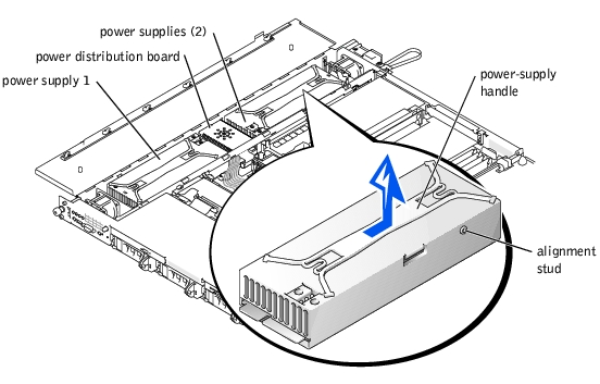
Removing and Replacing Power Supplies
This section describes how to install the following options:
This section also includes instructions for replacing system fans and power supplies, as well as the system battery.
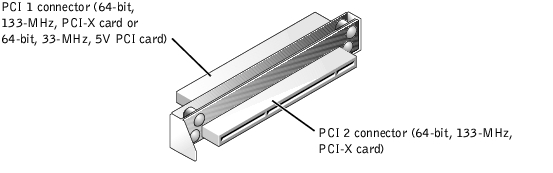
Up to two half-length, PCI-X expansion cards can be installed in the system, one on each side of the riser board assembly. See Figure 6-1. The riser board assembly consists of two riser boards permanently attached to each other with plastic standoffs. It plugs into twin riser connectors on the system board and is considered an extension of the system board. See Figure A-3.
The PCI slot locations are marked on the system board as PCI 1 and PCI 2. The PCI 1 connector on the riser board assembly is higher than the PCI 2 connector, because the PCI 1 card installs above the optional ROMB card.
Two different PCI card configurations are available:
Figure 6-1. Riser-Board Expansion-Card Connectors
To install an expansion card, perform the following steps.

|
CAUTION: Before you perform this procedure, you must turn off the system and disconnect it from its power source. For more information, see "Safety First—For You and Your System" in "Troubleshooting Your System." |
See the documentation that came with the expansion card for information about configuring the card, making internal connections, or otherwise customizing the card for your system.
Figure 6-2. Installing an Expansion Card
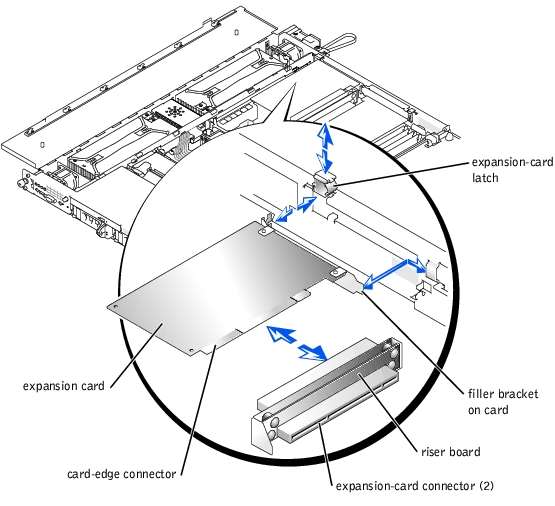
See the documentation supplied with the card for information about its cable connections.
To remove an expansion card, perform the following steps.
|
|
CAUTION: Before you perform this procedure, you must turn off the system and disconnect it from its power source. For more information, see "Safety First—For You and Your System" in "Troubleshooting Your System." |
 |
NOTE: Installing a filler bracket over an empty expansion slot is necessary to maintain Federal Communications Commission (FCC) certification of the system. The brackets also keep dust and dirt out of the system and aid in proper cooling and airflow inside the system. |
The four memory module sockets on the system board can accommodate from 256 MB to 8 GB of registered DDR SDRAM. See Figure 5-1.
The system is upgradable to 8 GB by installing combinations of 128-, 256-, 512-MB, 1-GB, or 2-GB registered memory modules. You can purchase memory upgrade kits as needed.
|
NOTE: The memory modules must be rated for 266-MHz operation. |
Starting with the socket closest to the edge of the system board, the memory module sockets are labeled DIMM_1A and DIMM_1B (bank 1) and DIMM_2A and DIMM_2B (bank 2). See Figure 6-3. When you install memory modules, follow these guidelines:
Figure 6-3. Memory Module Sockets
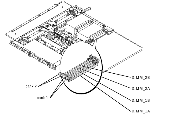
Table 6-1 illustrates several sample memory configurations based on these guidelines.
Table 6-1. Sample Memory Configurations
|
|
BANK1 |
BANK2 | ||
|---|---|---|---|---|
|
Total Desired Memory |
DIMM_1A |
DIMM_1B |
DIMM_2A |
DIMM_2B |
To perform a memory module upgrade to the system board, perform the following steps.
|
|
CAUTION: Before you perform this procedure, you must turn off the system and disconnect it from its power source. For more information, see "Safety First—For You and Your System" in "Troubleshooting Your System." |
Figure 6-3 identifies the memory module banks on the system board and shows the order of the socket designations.
After the system completes the POST routine, it runs a memory test. The system detects that the new memory does not match the system configuration information and displays an error message.
The system should have already changed the value in the System Memory setting to reflect the newly installed memory.
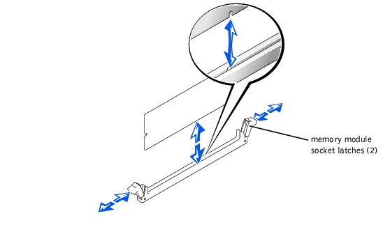
To install a memory module, perform the following steps:
Figure 6-4. Installing a Memory Module

The module and the socket are keyed to prevent misalignment.
When the memory module is properly seated in the socket, the latches on the memory module socket should align with the latches on the other sockets with memory modules installed.
To remove a memory module, press down and outward on the socket latches on each end of the socket until the memory module pops out of the socket. See Figure 6-5.
Figure 6-5. Removing Memory Modules
To take advantage of future options in speed and functionality, you can add a second microprocessor or replace either the primary or secondary microprocessor.
 |
NOTICE: The second microprocessor must be of the same type and speed as the first microprocessor. |
|
|
CAUTION: Ensure that you install only microprocessors purchased from Dell and intended for this system. Using a different microprocessor could cause data loss, system damage, or personal injury. |
Each microprocessor and its associated level 2 (L2) cache memory are contained in an FC-PGA2 package that is installed in a ZIF socket on the system board. The secondary microprocessor must have the same operating frequency and cache size as the primary microprocessor.
The following items are included in the microprocessor upgrade kit:
The following subsections describes how to remove and install a microprocessor in either the primary or secondary microprocessor connector.
|
|
CAUTION: Before you perform this procedure, you must turn off the system and disconnect it from its electrical outlet. For more information, see "Safety First—For You and Your System" in "Troubleshooting Your System." |
|
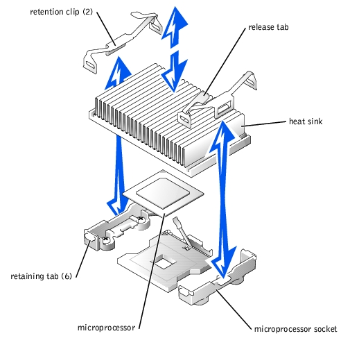
NOTICE: Never remove the heat sink from a microprocessor unless you intend to remove the microprocessor. The heat sink is necessary to maintain proper thermal conditions. |
|
|
CAUTION: The microprocessor chip and heat sink can become extremely hot. Be sure that the microprocessor has had sufficient time to cool before handling. |

|
NOTICE: Be careful not to bend any of the pins when removing the microprocessor. Bending the pins can permanently damage the microprocessor. |
If you are installing a new microprocessor, leave the release lever up so that the socket is ready for the new microprocessor.
Figure 6-7. Removing the Microprocessor

|
|
CAUTION: Before you perform this procedure, you must turn off the system and disconnect it from its electrical outlet. For more information, see "Safety First—For You and Your System" in "Troubleshooting Your System." |
|
NOTICE: Be careful not to bend any of the pins when unpacking the microprocessor. Bending the pins can permanently damage the microprocessor. |
If any of the pins on the microprocessor appear bent, see "Getting Help."
|
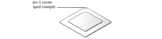
NOTICE: Identifying the pin-1 corners is critical to positioning the processor correctly. |
Figure 6-8. Pin-1 Identification
|
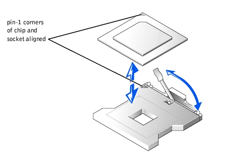
NOTICE: Positioning the microprocessor incorrectly can permanently damage the processor and the system when you turn on the system. |
Figure 6-9. Installing the Microprocessor
|
NOTICE: When placing the microprocessor in the socket, be sure that all of the pins on the processor go into the corresponding holes of the socket. Be careful not to bend the pins. |
Because the system uses a ZIF microprocessor socket, you do not need to use force (which could bend the pins if the microprocessor is misaligned). When the microprocessor is positioned correctly, it should drop down into the socket with minimal pressure.
Figure 6-10. Installing the Heat Sink
As the system boots, it detects the presence of the new microprocessor and automatically changes the system configuration information in the System Setup program.
See "Running the System Diagnostics" for information on running the diagnostics and troubleshooting any problems that may occur.
|
|
CAUTION: Before you perform this procedure, you must turn off the system and disconnect it from its power source. For more information, see "Safety First—For You and Your System" in "Troubleshooting Your System." |
|
|
CAUTION: Only trained service technicians are authorized to remove the system cover and access any of the components inside the system. See your System Information Guide for complete information about safety precautions, working inside the computer, and protecting against electrostatic discharge. |
|
NOTICE: To avoid possible data loss, back up all data on the hard drives before changing the mode of operation of the integrated SCSI controller from SCSI to RAID. |
Figure 6-11. Installing the ROMB Card and Backup Battery

|
|
CAUTION: Before you perform this procedure, you must turn off the system and disconnect it from its power source. For more information, see "Safety First—For You and Your System" in "Troubleshooting Your System." |
|
|
CAUTION: Only trained service technicians are authorized to remove the system cover and access any of the components inside the system. See your System Information Guide for complete information about safety precautions, working inside the computer, and protecting against electrostatic discharge. |
|
NOTICE: To avoid possible data loss, back up all data on the hard drives before changing the mode of operation of the integrated SCSI controller from SCSI to RAID. |
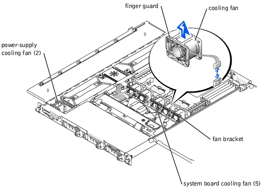
The five system-board cooling fans and two power-supply cooling fans must be installed and operational at all times. See Figure 6-12. A blinking amber LED next to a fan power connector indicates a faulty fan that needs to be replaced.
|
|
CAUTION: Only trained service technicians are authorized to remove the system cover and access any of the components inside the system. See your System Information Guide for complete information about safety precautions, working inside the computer, and protecting against electrostatic discharge. |
|
NOTICE: The fans are hot-pluggable. If a fan fails, replace it as soon as possible. Operating the system with a failed fan may cause the system to overheat and lock up. |
|
NOTE: After installing a new fan, allow up to 30 seconds for the system to recognize the fan and determine whether it is working properly. |
|
|
CAUTION: Only trained service technicians are authorized to remove the system cover and access any of the components inside the system. See your System Information Guide for complete information about safety precautions, working inside the computer, and protecting against electrostatic discharge. |
|
|
CAUTION: The connectors on the PDB contain high voltage. Do not remove the metal cover from the PDB or touch the connectors on the PDB or power supply. |
|
NOTICE: The power supplies are hot-pluggable. Remove and replace only one power supply at a time. |
|
|
CAUTION: Disconnect the AC cord for the failed power supply before removing the power supply. |
Figure 6-13. Removing a Power Supply
The system battery is a 3.0-V, coin-cell battery that maintains system configuration, date, and time information in a special section of memory when you turn off the system. The operating life of the battery ranges from 2 to 5 years, depending on how you use the system (for example, if you keep the system on most of the time, the battery gets little use and thus lasts longer). You may need to replace the battery if an incorrect time or date is displayed during the boot routine.
You can operate the system without a battery; however, the system configuration information maintained by the battery in NVRAM is erased each time you remove power from the system. Therefore, you must re-enter the system configuration information and reset the options each time the system boots until you replace the battery.
To replace the battery, perform the following steps.
|
|
CAUTION: Only trained service technicians are authorized to remove the system cover and access any of the components inside the system. See your System Information Guide for complete information about safety precautions, working inside the computer, and protecting against electrostatic discharge. |
|
|
CAUTION: There is a danger of a new battery exploding if it is incorrectly installed. Replace the battery only with the same or equivalent type recommended by the manufacturer. Discard used batteries according to the manufacturer's instructions. |
|
NOTICE: To avoid damage to the battery connector, you must firmly support the connector while installing or removing a battery. |
Figure 6-14. Installing the System Battery

|
NOTICE: To avoid damage to the battery connector, you must firmly support the connector while installing or removing a battery. |