|
Message
|
Causes
|
Corrective Actions
|
|---|
Address mark not found
| Faulty diskette/CD drive subsystem or hard-drive subsystem (defective system board). | See "Getting Help." |
Amount of available memory
limited to 256 MB!
| OS Install Mode is enabled in the System Setup program. | Disable the OS Install Mode in the System Setup program. See "Using the System Setup program" in the User's Guide. |
Alert! One or more of the
memory DIMMs are out of
rev.
| One or more of the installed DIMMs are not supported by the system. DIMMs must be registered DDR SDRAM rated for 266-MHz operation. | Ensure that all installed memory meets the system specifications. See "Installing Memory Modules" in "Installing System Options." |
Alert! Redundant memory
disabled! Memory
configuration does not
support redundant memory.
| One memory bank is not populated, or memory banks are different sizes. To support redundant memory, both banks must be populated, and all four DIMMs must be the same size. | Install identical DIMMs in all four memory banks. See "Installing Memory Modules" in "Installing System Options." |
Alert! Unsupported memory,
incomplete sets, or
unmatched sets.
The following memory
DIMM(s) have been
disabled: DIMM_xx
| DIMMs are installed in a mismatched pair, or one memory slot in a bank is empty. Memory must be installed in matched pairs. In a mismatched memory bank, neither DIMM is used. | Ensure that memory is installed in matched pairs. See "Installing Memory Modules" in "Installing System Options." |
Auxiliary device failure
| Mouse or keyboard cable connector loose or improperly connected; defective mouse or keyboard. | Check the mouse and keyboard cable connections. See "Troubleshooting External Connections" in "Troubleshooting Your System." If the problem persists, replace the mouse. If the problem persists, replace the keyboard. See "Getting Help." |
Attachment failed to
respond.
| Diskette drive or hard-drive controller cannot send data to associated drive. | Reboot the system. If you receive an error message from the SCSI, RAID, or diskette controller, see "Getting Help." If no error message appears at system boot, reseat all drives. If the problem persists, see "Getting Help." |
Bad error-correction code
(ECC) on disk read.
Controller has failed.
| Faulty diskette drive, tape drive, or hard-drive subsystem (defective backplane board). | Reseat all drives and reboot the system. If the error message reappears, see "Getting Help." |
BIOS Update Attempt
Failed!
| Remote BIOS update attempt failed. | Retry the BIOS update. If the problem persists, see "Getting Help." |
Caution! NVRAM_CLR jumper
is installed on system
board - please run SETUP
program.
| Incorrect configuration settings in System Setup program, NVRAM_CLR jumper is installed, or faulty system battery. | Check the System Setup configuration settings. See "Using the System Setup Program" in the User's Guide. Remove the NVRAM_CLR jumper. See Figure A-2 for jumper location. Replace the battery. See "Replacing the System Battery" in "Installing System Options." |
CPUs with different cache
sizes detected.
| Two different types of microprocessors are installed. | Install a correct version of the microprocessor so that both microprocessors have the same level 2 cache size. See "Installing Microprocessors" in "Installing System Options." |
Data error
| Faulty diskette, diskette drive, or hard drive. | Replace the diskette. Reseat all drives and reboot the system. If the error message reappears, see "Getting Help." |
Decreasing available
memory
| One or more memory modules improperly seated or faulty. | Remove and reseat the memory modules. See "Installing Memory Modules" in "Installing System Options." If the problem persists, replace the memory modules. If the problem persists, see "Getting Help." |
Diskette drive 0 seek
failure
Diskette drive 1 seek
failure
| Faulty or improperly inserted diskette or incorrect configuration settings in System Setup program. | Reseat the diskette drive and replace the diskette. See "Installing a Diskette Drive" in "Installing Drives." Run the System Setup program to correct the diskette drive type. See "Using the System Setup Program" in the User's Guide. |
Diskette read failure
| Faulty diskette, or faulty or improperly connected diskette drive. | Reseat the diskette drive and replace the diskette. See "Installing a Diskette Drive" in "Installing Drives." |
Diskette subsystem reset
failed
| Faulty diskette/CD drive controller (defective system board). | Replace the system board. See "Getting Help." |
Diskette write protected
| Diskette write-protect feature is enabled. | Disable the write-protect feature on the diskette. |
Drive not ready
| Diskette missing from or improperly inserted into the diskette drive. | Reinsert the diskette into the drive. |
ECC memory error
| Improperly seated or faulty memory modules. | Remove and reseat the memory modules. See "Installing Memory Modules" in "Installing System Options." If the problem persists, replace the memory modules. If the problem persists, see "Getting Help." |
Embedded server management
error
Embedded server management
is not present
| Embedded server management memory may be temporarily corrupted. | To clear the embedded server management memory, shut down the system, disconnect the power cord(s), wait approximately 30 seconds, and then reconnect the power cord(s) and restart the system. If the problem persists, see "Getting Help." |
Error: Dell Remote Access
Controller initialization
failure
| Defective RAC or system board. | Replace the RAC. See the documentation that came with the RAC. If the problem persists, you may need to replace the system board. See "Getting Help." |
Gate A20 failure
| Faulty keyboard controller (defective system board). | Replace the system board. See "Getting Help." |
General failure
| Application program or operating system failure. | Reboot. If the message reappears, see your software documentation. |
Hard disk controller
failure
Hard disk read failure
| Incorrect configuration settings in the System Setup program, improperly connected hard drive, or faulty hard-drive controller subsystem (defective system board). | Check the hard-drive configuration settings in the System Setup program. See "Using the System Setup Program" in the User's Guide. Reinstall the hard drive. See "Installing SCSI Hard Drives" in "Installing Drives." |
Invalid configuration
information - please run
SETUP program.
| Incorrect configuration settings in the System Setup program, the NVRAM_CLR jumper is installed, or the system battery is faulty. | Check the System Setup configuration settings. See "Using the System Setup Program" in the User's Guide. Remove the NVRAM_CLR jumper. See Figure A-2 for jumper location. Replace the battery. See "Replacing the System Battery" in "Installing System Options." |
Invalid memory
configuration detected.
Potential for data
corruption exists!
| Memory modules are not installed in matched pairs. | Install memory modules in matched pairs. See "Installing Memory Modules" in "Installing System Options." |
Invalid NVRAM
configuration, resource
re-allocated
| System configuration data has been ignored. | Check the System Setup configuration settings. See "Using the System Setup Program" in the User's Guide. |
I/O card parity interrupt
at address
| Expansion card(s) is improperly installed or faulty. | Reinstall the expansion card(s). See "Installing Expansion Cards" in "Installing System Options." If the problem persists, replace the expansion card(s). |
Keyboard controller
failure
| Defective keyboard/mouse controller (defective system board). | Replace the system board. See "Getting Help." |
Keyboard data line failure
Keyboard stuck key failure
Keyboard clock line
failure
Keyboard failure
| Keyboard cable connector is loose or improperly connected; defective keyboard; defective keyboard/mouse controller (defective system board). | Check the keyboard cable connection. Replace the keyboard. If the problem persists, replace the system board. See "Getting Help." |
Memory allocation error
| Memory module(s) is not connected properly, or an application program or the operating system failed. | Reseat the modules. See "Installing Memory Modules" in "Installing System Options." Reboot the system. If the message reappears, see your software documentation. |
Memory address line
failure at address, read
value expecting value
Memory high data line
failure at start address
to end address
Memory high address line
failure at start address
to end address
Memory double word logic
failure at start address
to end address
Memory double word logic
failure at address, read
value expecting value
Memory odd/even logic
failure at start address
to end address
Memory odd/even logic
failure at address, read
value expecting value
Memory write/read failure
at address, read value
expecting value
Memory write/read failure
at start address to end
address
| Faulty or improperly seated memory modules or defective system board.
| Remove and reseat the memory modules. See "Installing Memory Modules" in "Installing System Options." If the problem persists, replace the memory modules. If the problem persists, see "Getting Help." |
Memory parity failure at
start address to end
address
Memory parity error at
address
| Improperly seated or faulty memory modules. | Remove and reseat the memory modules. See "Installing Memory Modules" in "Installing System Options." If the problem persists, replace the memory modules. If the problem persists, see "Getting Help." |
No boot device available
| Faulty diskette, diskette/CD drive subsystem, hard drive, or hard-drive subsystem; no boot disk in drive A. | Replace the diskette or the hard drive. See "Installing Drives." If the problem persists, replace the system board. See "Getting Help." |
No boot sector on hard-
disk
| No operating system on the hard drive. | Check the hard-drive configuration settings in the System Setup program. See "Using the System Setup Program" in the User's Guide. |
No timer tick interrupt
| Defective system board. | Replace the system board. See "Getting Help." |
No PXE-capable device
available
| <F12> was pressed during POST and no PXE devices are detected. | Check the cables connected to the NICs. Check the configuration settings in the System Setup program for the NICs. See "Using the System Setup Program" in the User's Guide. |
Non-system disk or disk
error
| Faulty diskette, diskette drive subsystem, or hard-drive subsystem. | Replace the diskette. Reseat all drives and reboot the system. If the error message reappears, see "Getting Help." |
Not a boot diskette
| No operating system on diskette. | Use a bootable diskette. |
PCI BIOS failed to install
| PCI device (option ROM) checksum failure is detected during shadowing. | Contact the PCI device manufacturer to obtain a suitable replacement PCI option ROM. Follow the manufacturer's instructions to install the option ROM. |
Plug & Play Configuration
Error
| Error encountered when initializing the PCI device, or the system board is defective. | Install the NVRAM_CLR jumper and reboot the system. If the problem persists, replace the system board. See "Getting Help." |
Plug & Play Configuration
Error PCI_n
| Error encountered when initializing the PCI adapter. | Install the NVRAM_CLR jumper and reboot the system. If the problem persists, replace the specified expansion-card. See "Installing Expansion Cards" in "Installing System Options." If the problem persists, replace the system board. See "Getting Help." |
Primary backplane error
| Improperly attached or missing backplane. | Ensure that the SCSI backplane board is fully seated. See "Troubleshooting SCSI Hard Drives" in "Troubleshooting Your System." |
Primary IDE device 0 not
found
Primary IDE device 1 not
found
| Improperly connected or missing IDE device. | Ensure that the device's interface cable is securely connected to the SCSI backplane board. Replace the device. If the problem persists, see "Getting Help." |
Processor 1 internal error
Processor 2 internal error
| Defective microprocessor or system board (reported by the NMI handler).
| Replace the specified microprocessor. See "Installing Microprocessors" in "Installing System Options." If the problem persists, replace the system board. See "Getting Help." |
Processor bus error
PCI bus error
IMB bus error
| Defective system board (reported by the NMI handler). | Replace the system board. See "Getting Help." |
Processor x is not a
533-MHz system bus
processor
This system bus speed is
not supported on this
system board.
| This system supports only Intel® Xeon™ 533-MHz front-side-bus (system bus) processors. | Reboot the system. If you receive beep code 4-4-3 (processor frequency mismatch), replace processor x with a supported processor. See "Installing Microprocessors" in "Installing System Options." If a beep code does not occur at system boot, turn off the system, install the NVRAM_CLR jumper, and reboot the system. If the message reappears, see "Getting Help." |
Read fault
Requested sector not found
| Faulty diskette, diskette-drive subsystem, or hard-drive subsystem. | Replace the diskette, or reseat all drives and reboot the system. If the message reappears, see "Getting Help." |
Reset failed
| Improperly connected diskette/tape drive, hard drive, or power cable. | Check the drive and cable connections, and reset the system again. If the message reappears, see "Getting Help." |
ROM bad checksum = address
| Expansion card improperly installed or faulty. | Reinstall the expansion card. See "Installing Expansion Cards" in "Installing System Options." |
Sector not found
Seek error
Seek operation failed
| Defective sectors on diskette or hard drive. Faulty diskette, diskette-drive subsystem, or hard-drive subsystem. | Replace the diskette, or reseat all drives and reboot the system. If the message reappears, see "Getting Help." |
Shutdown failure
| Defective system board. | Replace the system board. See "Getting Help." |
System backplane error
| Improperly attached or missing SCSI backplane. | Check that the SCSI backplane board is fully seated. See "Troubleshooting SCSI Hard Drives" in "Troubleshooting Your System." |
System halted! Must power
down.
| Wrong password entered too many times. | Reboot the system and enter the correct password. If the problem persists, see "Disabling a Forgotten Password" in "Jumpers and Connectors." |
System parity error
| Defective expansion card(s) or improperly seated or faulty memory modules (reported by the NMI handler). | Replace the expansion cards one at a time until the error is corrected. See "Installing Expansion Cards" in "Installing System Options." Remove and reseat the memory modules. See "Installing Memory Modules" in "Installing System Options." If the problem persists, replace the memory modules. If the problem persists, see "Getting Help." |
The following memory DIMMs
are unsupported: DIMM_xx.
This system only supports
266 MHz DIMMs.
| One or more of the installed DIMMs has a frequency less than 266 MHz. System memory must be rated for 266 MHz. | Replace lower-speed DIMM(s) with modules rated for 266-MHz operation. See "Installing Memory Modules" in "Installing System Options." |
Time-of-day clock stopped
| Defective battery or faulty chip (defective system board). | Replace the system battery. See "Replacing the System Battery" in "Installing System Options." If the problem persists, replace the system board. See "Getting Help." |
Time-of-day not set -
please run SETUP program
| Incorrect Time or Date settings or defective system battery. | Check the Time and Date settings. See "Using the System Setup Program" in the User's Guide. If the problem persists, replace the system battery. See "Replacing the System Battery" in "Installing System Options." If the problem persists, replace the system board. See "Getting Help." |
Timer chip counter 2
failed
| Defective system board. | Replace the system board. See "Getting Help." |
Unsupported CPU
combination
| Microprocessor combination is not supported by the system. | Install a supported microprocessor combination. See "Installing Microprocessors" in "Installing System Options." |
Unsupported CPU stepping
detected.
| Microprocessor is not supported by the system. | Install the correct version of the microprocessor in the specified microprocessor socket. See "Installing Microprocessors" in "Installing System Options." |
Utility partition not
available
| <F10> key was pressed during POST, but no utility partition exists on the boot hard drive. | Create a utility partition on the boot hard drive. See "Using the Dell OpenManage Server Assistant CD" in your User's Guide. |
Warning: Detected mode
change from SCSI to RAID on
channel x of the embedded
RAID subsystem.
Warning: Detected missing
RAID hardware for the
embedded RAID subsystem.
Data loss will occur!
Press Y to switch mode to
SCSI, press any other key
to disable both channels.
Press Y to confirm the
change; press any other
key to cancel.
| Type of controller has changed since previous system boot. | Back up information on the hard drives before changing the type of controller used with the drives. |
Warning: Detected mode
change from RAID to SCSI on
channel x of the embedded
RAID subsystem.
Warning: Detected missing
RAID hardware for the
embedded RAID subsystem.
Data loss will occur!
Press Y to switch mode to
SCSI, press any other key
to disable both channels.
Press Y to confirm the
change; press any other
key to cancel.
| Type of controller has changed since previous system boot. | Back up information on the hard drives before changing the type of controller used with the drives.
|
Warning! Embedded SCSI-
RAID error
| Faulty RAID adapter, or ROMB card firmware is either corrupted or is the wrong version. | Reseat the ROMB card. See "Installing a ROMB Card" in "Installing System Options." Reboot the system. If the message reappears, see "Getting Help." |
Warning! Embedded SCSI-
RAID firmware is not
present!
| ROMB card firmware is either corrupted or is the wrong version. | Reseat the ROMB card. See "Installing a ROMB Card" in "Installing System Options." Reboot the system. If the message reappears, see "Getting Help." |
Warning! Firmware is out-
of-date, please update
| Out-of-date firmware. | Update the system firmware. See "Using the Dell OpenManage Server Assistant CD" in your User's Guide for information about updating the system firmware. |
Warning! No microcode
update loaded for
processor x
| BIOS is not current. | Update the BIOS, but do not turn the system off before the update. See "Using the System Setup Program" in the User's Guide. |
Warning! Remote Access
Controller command failure
| Command protocol failure between the RAC and ESM3. | Reseat the RAC in its system board connector. See "Removing and Replacing the Optional Front Bezel" (if necessary) and "Opening the System Covers" in "Troubleshooting Your System." See Figure A-3 in "Jumpers and Connectors" for the location of the RAC Ethernet connector. If the message reappears, see "Getting Help." |
Warning! Unsupported
Remote Access Controller
firmware version detected
| RAC firmware is corrupted or is the wrong version. | Reseat the RAC in its system board connector. See "Removing and Replacing the Optional Front Bezel" (if necessary) and "Opening the System Covers" in "Troubleshooting Your System." See Figure A-3 in "Jumpers and Connectors" for the location of the RAC connector. If the message reappears, see "Getting Help." |
Write fault
Write fault on selected
drive
| Faulty diskette or hard drive. | Replace the diskette or hard drive. See "Installing Drives." |
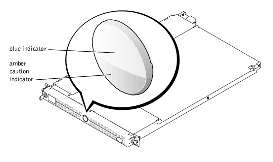
 Indicators on the Optional Bezel