Back to Contents Page
Dell™ PowerEdge™ 1750 Systems
Installation and Troubleshooting Guide
 Installing SCSI Hard Drives
Installing a CD Drive
Installing a Diskette Drive
Connecting External SCSI Hard Drives
Connecting an External SCSI Tape Drive
Configuring the Boot Device
Your system features three internal hard-drive bays to accommodate up to three SCSI hard drives. Your system also features two peripheral bays that can be used for an optional CD drive and a 3.5-inch diskette drive. This section contains instructions for replacing these devices as well as upgrading the system by installing a host adapter card.
This subsection describes how to install and configure SCSI hard drives in the system's internal hard-drive bays and how to upgrade the system by installing a host adapter expansion card.
The internal hard-drive bays provide space for up to three 1-inch SCSI hard drives. These drives connect to the system board through the SCSI backplane board.
SCSI hard drives are supplied in special drive carriers that fit in the hard-drive bays.
 |
NOTICE: Before attempting to remove or install a drive while the system is running, see the
documentation for the host adapter to ensure that the host adapter is configured correctly to
support hot-pluggable drive removal and insertion.
|
 |
NOTE: It is recommended that you use only drives that have been tested and approved
for use with the SCSI backplane board.
|
You may need to use different programs than those provided with the operating system to partition and format SCSI hard drives.
|
NOTICE: Do not turn off or reboot your system while the drive is being formatted. Doing so can
cause a drive failure.
|
When you format a high-capacity SCSI hard drive, allow enough time for the formatting to be completed. Long format times for these drives are normal. A 9-GB hard drive, for example, can take up to 2.5 hours to format.
|
NOTICE: Hot-plug drive installation is not supported for systems without the optional ROMB
card.
|
- If the system does not have a ROMB card installed, shut down the system.
- Remove the front bezel, if attached. See "Removing and Replacing the Optional Front
Bezel" in "Troubleshooting Your System."
- Open the hard-drive handle. See Figure 7-1.
Figure 7-1. Installing a SCSI Hard Drive
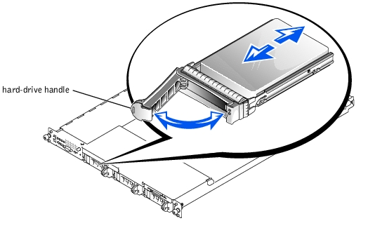
- Insert the hard drive into the drive bay. See Figure 7-1.
- Close the hard-drive handle to lock the drive in place.
- Replace the front bezel, if it was removed in step 3.
- If the hard drive is a new drive, run the SCSI Controllers test in the system
diagnostics.
|
NOTICE: Hot-plug drive installation is not supported for systems without the optional ROMB
card.
|
- If the system does not have a ROMB installed, shut down the system.
- Remove the front bezel, if attached. See "Removing and Replacing the Optional Front
Bezel" in "Troubleshooting Your System."
- For systems with a ROMB card, power down the hard-drive bay and wait until the
SCSI hard-drive indicators on the drive carrier signal that the drive can be removed
safely.
If the drive has been online, the green power on/fault indicator will flash as the drive is powered down. When both drive indicators are off, the drive is ready for removal.
- Open the hard-drive handle to release the drive.
- Slide the hard drive out until it is free of the drive bay.
- Replace the front bezel, if it was removed in step 2.
The optional CD drive is contained in a carrier that slides into the peripheral bay.

|
CAUTION: Only trained service technicians are authorized to remove the system cover and access any of the components inside the system. See your System Information Guide for complete information about safety precautions, working inside the computer, and protecting against electrostatic discharge. |
- Turn off the system, including any attached peripherals, and disconnect the system
from the electrical outlet.
- Remove the front bezel, if attached. See "Removing and Replacing the Optional Front
Bezel" in "Troubleshooting Your System."
- Open the system covers. See "Opening the System Covers" in "Troubleshooting Your
System."
- If a filler plate is installed in the drive bay, remove it now.
- If the drive carrier and the drive were supplied separately, install the drive in the
carrier. See Figure 7-2.
Figure 7-2. Installing a CD Drive in a Drive Carrier
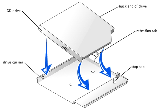
- Match the back end of the drive with the back end of the carrier, which has a
retention tab.
- Fit the right edge of the CD drive into the carrier tray, pressing the drive firmly
backward against the stop tab near the right rear corner of the carrier.
- Lower the left side of the drive into the carrier until the drive snaps into place.
- Slide the drive into the peripheral bay until it is fully inserted. See Figure 7-3.
Figure 7-3. Installing a CD Drive
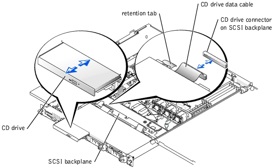
- Connect the CD drive data cable to the CD drive and to the CD drive connector on
the SCSI backplane. See Figure A-4.
- Close the system covers. See "Closing the System Covers" in "Troubleshooting Your
System.
- Replace the front bezel, if it was removed in step 2. See "Removing and Replacing the
Optional Front Bezel" in "Troubleshooting Your System."
- Reconnect the system and peripherals to their electrical outlets.
The optional diskette drive is contained in a carrier that slides into the peripheral bay. Perform the following steps to install a diskette drive.
|
|
CAUTION: Only trained service technicians are authorized to remove the system cover and access any of the components inside the system. See your System Information Guide for complete information about safety precautions, working inside the computer, and protecting against electrostatic discharge. |
- Turn off the system, including any attached peripherals, and disconnect the system
from the electrical outlet.
- Remove the front bezel, if attached. See "Removing and Replacing the Optional Front
Bezel" in "Troubleshooting Your System."
- Open the system covers. See "Opening the System Covers" in "Troubleshooting Your
System."
- If a filler plate is installed in the drive bay, remove it now.
- If the carrier and the drive were supplied separately, install the drive in the carrier. See
Figure 7-4.
Figure 7-4. Installing a Diskette Drive in a Carrier
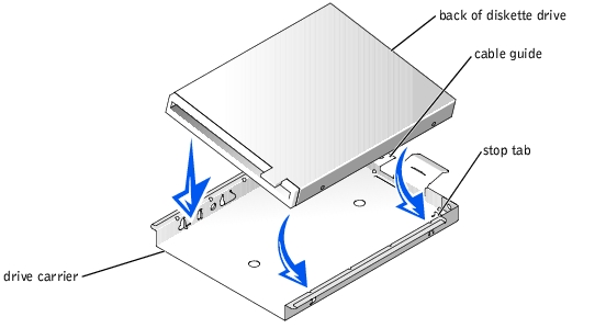
- Fit the right edge of the diskette drive into the carrier tray, pressing the drive
against the stop tab at the back of the carrier.
- Lower the left edge of the drive into the carrier until the drive snaps into place.
- Attach the end of the ribbon cable labeled "FLOPPY" to the back of the diskette
drive, and then insert the cable through the slot in the cable guide at the back of
the carrier.
- Slide the drive into the peripheral bay until it is fully seated. See Figure 7-5.
Ensure that you do not damage the ribbon cable at the back of the drive.
Figure 7-5. Installing a Diskette Drive
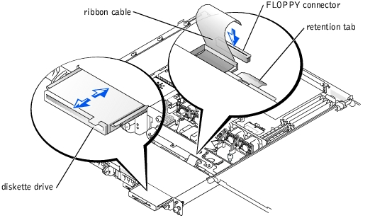
- Connect the other end of the ribbon cable to the diskette drive connector on the SCSI
backplane. See Figure A-4.
- Close the system covers. See "Closing the System Covers" in "Troubleshooting Your
System."
- Replace the front bezel, if it was removed in step 2. See "Removing and Replacing the
Optional Front Bezel" in "Troubleshooting Your System."
- Reconnect the system and peripherals to their electrical outlets.
Follow these general guidelines when connecting external SCSI hard drives to the external SCSI connector on the system's back panel or to a SCSI controller card.
|
|
CAUTION: Before you perform this procedure, you must turn off the system and disconnect it from its power source. For more information, see "Safety First—For You and Your System" in "Troubleshooting Your System." |
|
|
CAUTION: Only trained service technicians are authorized to remove the system cover and access any of the components inside the system. See your System Information Guide for complete information about safety precautions, working inside the computer, and protecting against electrostatic discharge. |
- Turn off the system, including any attached peripherals, and disconnect the system
from the electrical outlet.
- If you are installing a SCSI controller card, install the card now. See "Installing
Expansion Cards" in "Installing System Options."
- Connect the external SCSI devices to the external SCSI connector on the system's
back panel.
If you are attaching multiple external SCSI devices, daisy-chain the devices using the cables shipped with each device.
- Reconnect the system to an electrical outlet and turn it on.
- Connect the external device(s) to electrical outlet(s) and turn them on.
- Install any required SCSI device drivers. See "Installing and Configuring SCSI Drivers"
in the User's Guide.
- Test the SCSI devices.
This subsection describes how to configure and install an external SCSI tape drive with an add-in PCI controller card.
|
NOTE: The integrated SCSI controller does not support mixed mode (one channel
SCSI and one channel RAID). For this reason, in a system with RAID, Dell does not
support an external tape drive connected to the external SCSI controller.
|
|
|
CAUTION: Only trained service technicians are authorized to remove the system cover and access any of the components inside the system. See your System Information Guide for complete information about safety precautions, working inside the computer, and protecting against electrostatic discharge. |
- Turn off the system, including any attached peripherals, and disconnect the system
from the electrical outlet.
- Ground yourself by touching an unpainted metal surface on the back of the system,
unpack the drive, and compare the jumper and switch settings with those in the
documentation that came with the drive.
- Unpack the tape drive and controller card and configure the tape drive according to
the documentation that came with the tape drive, based on the following guidelines:
- Each device attached to a SCSI host adapter must have a unique SCSI ID
number. (Narrow SCSI devices use IDs 0 to 7; wide SCSI devices use IDs from 0
to 15).
A SCSI tape drive is typically configured as SCSI ID 6.
|
NOTE: There is no requirement that SCSI ID numbers be assigned sequentially or that
devices be attached to the cable in order by ID number.
|
- SCSI logic requires that the two devices at opposite ends of a SCSI chain be
terminated and that all devices in between be unterminated. Therefore, you
enable the tape drive's termination if it is the last device in a chain of devices (or
sole device) connected to the SCSI controller.
- Install the controller card in an expansion slot. See "Installing Expansion Cards" in
"Installing System Options."
- Connect the tape drive's interface/DC power cable to the connector on the controller
card supplied with the tape drive.
- Reconnect the system and peripherals to their electrical outlets, and turn them on.
- Perform a tape backup and verification test with the drive as instructed in the software
documentation that came with the drive.
If you plan to boot the system from a hard drive, the drive must be attached to the primary (or boot) controller. The device that the system boots from is determined by the boot order specified in the System Setup program.
The System Setup program provides options that the system uses to scan for installed boot devices. See your system's User's Guide for information about the System Setup program.
Back to Contents Page