5 FIST: a first instruction set
\(\newcommand{\la}{\lambda} \newcommand{\Ga}{\Gamma} \newcommand{\ra}{\rightarrow} \newcommand{\Ra}{\Rightarrow} \newcommand{\La}{\Leftarrow} \newcommand{\tl}{\triangleleft} \newcommand{\ir}[3]{\displaystyle\frac{#2}{#3}~{\textstyle #1}}\)
This chapter continues the development begun in the previous chapter of describing the processor in greater detail (and issues arising from its design) through refined versions of machine languages.
5.1 A more realistic processor
There are two important properties of physical memory that we have not taken into account, and we do so now. One of them is a fixed size or width for each word of memory. A 32-bit architecture, as discussed briefly earlier (and in a bit more detail in IYMLC) has 32-bit words. Although desktops and laptops being produced now use a 64-bit architecture, the difference is not pedagogically significant, and it’s easier to talk about and visualize 32-bit words.
The 32 bits in a word may be interpreted in different ways: as one instruction, as a natural number, as an integer, as four characters from a limited character set, and so on. Rather than have disjoint sets of bit patterns for each of these uses, they all overlap. So the interpretation of a word is dependent on context.
Because we need to refer to different bits in a word, we need some terminology.
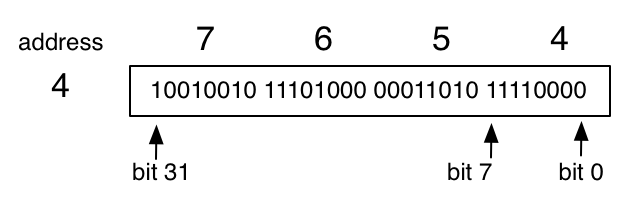
The leftmost bit in a word, the most significant bit (MSB), is bit 31; the rightmost bit, the least significant bit, is bit 0. The bits are grouped into four bytes of 8 bits each. The one containing bits 7 through 0 is sometimes called the least significant byte. Since we often have to refer to ranges of bits, we will use the convention that 31:24 refers to bits 31 to 24 (the most significant byte).
Each byte has an address, which is a natural number that is itself representable using 32 bits (the usual binary encoding). The address of a word is the address of its least significant byte, and the addresses of bytes in a word increase from right to left (this is known as a little-endian architecture, and the other direction is big-endian). Therefore addresses of words are always divisible by 4.
Writing out the 32 bits in a word would take a lot of space, so we usually use hexadecimal or hex (base 16), in which the digits are 0 through 9 followed by A through F. One hex digit can represent four bits, so eight hex digits can represent any 32-bit pattern. Four bits is half a byte, so this is sometimes called a nibble. We can leave leading zeroes off or include them, as is appropriate. Conveniently, Racket lets us use this notation, so that #xA0, #b10100000, and 160 all represent the same value.
Operations on bits are often expressed in logical terms, where the bit 1 represents true and the bit 0 represents false. So the AND of 1 and 0 would be 0. Other operations include OR and XOR (exclusive-OR, which is like OR, except that XOR of 1 and 1 is 0). These operations are often extended to bytes and words in a "bitwise" fashion. The bitwise AND of 11001100 and 10101010 is 10001000.
We discussed the representation of numbers using bits in Part I; let’s quickly review that material. The bit pattern \(b_k b_{k-1}\ldots b_1 b_0\), where each \(b_i\) is either 0 or 1 (\(b_k\) is 1), represents the natural number \(\sum_{i=0}^k b_i 2^i\). This is binary notation.
As an example, \(5\) is represented by \(101\), because \(5=1\cdot2^2+0\cdot 2^1+1\cdot 2^0\). If \(k<31\), we can add zeros on the left to make a 32-bit pattern; if \(k>31\), we cannot represent the corresponding number in 32 bits.
The representation of negative numbers is a bit more complex; again, refer to Part I for a full development. Forgetting about the 32-bit restriction for the moment, let us consider adding an infinite number of zeros on the left (using the left-infinite sequence \(\ldots 0\)) to any bit pattern starting with 1 representing a natural number.
We can consider building up this number starting with \(\ldots 0\) by adding bits on the right. Adding a 0 on the right doubles the number; adding 1 on the right doubles and adds 1. Since we said that \(b_k\) had to be 1, we can’t start by adding a 0 on the right, but we can do this after the first 1 is added. As an example, starting with \(\ldots 0\), representing 0, we add 1 on the right to get \(\ldots 0 1\), representing 1; then we add 0, to get \(\ldots 0 1 0\), representing 2; then we add 1, to get \(\ldots 0 1 0 1\), representing 5. Keeping only the rightmost 32 bits gives us the representation discussed above.
Now let us see how to represent negative numbers. The left-infinite sequence of ones, \(\ldots 1\), will represent the number \(-1\). We can add bits on the right as before, using the same interpretation as before. Just as we had to start by adding 1 to \(\ldots 0\), we have to start by adding 0 to \(\ldots 1\). As an example, starting with \(\ldots 1\), representing -1, we add 0 on the right to get \(\ldots 1 0\), representing -2; then we add 1, to get \(\ldots 1 0 1\), representing -3; then we add 0, to get \(\ldots 1 0 1 0\), representing -6. Keeping only the rightmost 32 bits gives us the two’s complement representation of integers.
Racket provides support for considering Racket integers as sequences of bits in just this fashion and for performing shift and bitwise operations on the resulting left-infinite sequences. Details can be found in section 4.3.2.6 of the Racket Reference. These will be useful in working with FIST concepts within Racket.
The other important property of physical memory that drives processor design is that large memories are slow; that is, the time it takes to reference a location, either for reading or for writing, is relatively long compared to the time it takes to do other things. Smaller memories are faster. Processors operate using a central clock whose ticks are called cycles. Some instructions can be executed in one or two cycles, but memory accesses can take tens or even hundreds of cycles.
Consequently, rather than having operations use three memory addresses (two sources and one destination, as in PRIMP), it makes sense to move currently-used values from large, slow memory to a smaller, faster memory that can be accessed in a few cycles. These faster locations are usually called registers. (There are, in fact, other levels of memory as well, such as instruction and data caches, and virtual memory on disk, but these are typically handled by the hardware and/or operating system and not by programmers.)
Here is what the revised machine architecture looks like. It is typically called a "von Neumann architecture", after the man who described it in an influential written report in the 1940’s, though the ideas came from many sources and many independent researchers and developers.
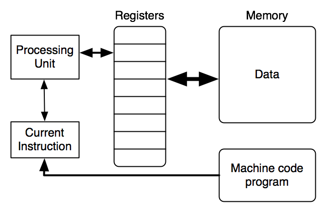
The fetch-execute cycle (another common feature of von Neumann architectures) is the same as before.
5.2 The FIST architecture
The machine I will describe, which I’ll call FIST (the "backronym" is First Instruction Set) has no actual physical implementation, but it is a simplification of a real machine called ARM, first developed in the 1980’s, and whose current versions are the main processors in the vast majority of portable devices (cellphones, etc.) on the planet. ARM architectures are an example of RISC (Reduced Instruction Set Computing), a concept originating in the 1980’s that focussed on machines with a simpler instruction set in order to create hardware that used less energy and was faster. The Intel x86 architecture that is used in the majority of desktops, laptops, and larger servers is CISC (the first C stands for Complex), because features accreted over decades, with backward compatibility preserved. However, many current x86 hardware designs have a RISC-like core at their heart.
FIST is based on the 32-bit ARMv3 instruction set designed by Sophie Wilson. It has a number of unusual features, which fit well with the alternative approach of this flânerie. The most recent architecture, ARMv9, is 64-bit, somewhat more conventional, and more complex.
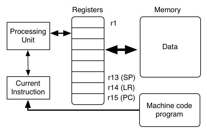
In the FIST architecture, there are 16 registers. The registers are called r0 through r15. r15 is the program counter (PC, and we may use pc in instructions). r14 has special status in one instruction, and is called the link register (LR, and we may use lr in instructions). The rest of the registers are general-purpose, though by convention r13 is often used as the stack pointer (SP, and we may use sp in instructions). The diagram shows a register holding the current instruction, but this is internal to the hardware and not referred to by the instruction set, as the machine-language programmer does not need to directly manipulate it.
As with PRIMP, we can build a FIST machine simulator in Racket, though ARM simulators are available (not to mention real ARM hardware).
A program is now a sequence of instructions, each instruction encoded into one word of memory. Every possible instruction is represented by a 32-bit pattern, but not all bit patterns represent possible instructions. Note that the distinction between code (instructions) and data that we maintained with PRIMP has been erased. In order to execute one instruction, both a physical hardware processor and our software simulator would have to decode a bit pattern to extract information. The design of the instruction set is heavily influenced by practical hardware design considerations, and the result may not be the easiest to understand by the assembly-language programmer, or the easiest to program a simulator for.
I will describe a more readable assembly-language format (similar to PRIMP) and its encoding. Not every instruction will be described here; there is a reference at the end of the chapter.
As an example, (add r4 r3 r2) sets register 4 to the result of adding registers 3 and 2, where operands and result are 32-bit two’s complement integers. This looks a lot like a PRIMP instruction, but it is referring to registers instead of memory. The encoding of (add r4 r3 r2) will be xE0834002. The representation of an instruction using Racket lists is for our convenience. Usually a text representation like ADD r4,r3,r2 is used.
5.2.1 Status bits and conditional execution
FIST, unlike PRIMP, has no memory-to-memory instructions. It has a few instructions to move information between memory and registers, and more instructions that work only with registers. I’ll start by describing the data processing instructions that work with registers. In order to do this, I have to first discuss the special status of r15, the PC.
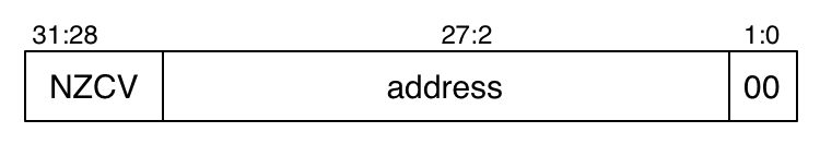
Because one instruction is stored in one word, the PC always contains a word address, so its lower two bits are always 0. A real ARM architecture uses these bits for other purposes and they are not used when fetching the next instruction. The most significant four bits are also not used; that is, the address of the next instruction to be executed is calculated by using bits 27:2 of the PC, with all other bits being 0 for the address calculation.
Bits 31:28 of the PC are used for status bits that describe the effect of recently-executed instructions. In order from most significant, they are N (negative), Z (zero), C (carry), and V (overflow). If a status bit has value 1, this represents the logical value true, and we say it is set. Bit value 0 represents the logical value false, and we say it is unset. The carry and overflow bits are both affected by arithmetic operations, but the carry bit can also be affected by shift/rotate operations described below.
In modern ARM architectures, and many others, the status bits are in a separate register called the status register. Early ARM architectures placed status bits in the PC, because memories were much smaller then (especially in the devices for which the design was intended), and the full address space was not needed.
The status bits can be used for conditional execution. In PRIMP, and in most other instruction sets, there are conditional branch instructions. But in FIST (and all ARM architectures), every instruction can be executed conditionally. We indicate the conditions by a condition code in bits 31:28 of the encoded instruction. Thus there are sixteen possible condition codes.
Your first thought might be that the instruction is executed only if the four bits of the condition code match the four status bits. But this is not the way it works. Some of the combinations are not useful, and sometimes we don’t care about some of the status bits.
The sixteen condition codes are represented in the assembly language by two-letter suffixes on an instruction. Examples include al for "always", nv for "never", and eq for "equal" (this one means that the Z status bit is set, which would be the case after the subtraction or comparison of two equal numbers). So (addeq r4 r3 r2) is like the earlier example, but it is executed only if the Z status bit is set (otherwise it has no effect and the next instruction is fetched). The "always" suffix is implied if it is left off, so the earlier example still works. The complete list of condition codes and their meanings is given in the reference at the end of the chapter.
There are five types of instructions: data processing, load and store, branch, software interrupt, and multiple load and store. I will describe them in this order.
5.2.2 Data processing instructions

All data processing instructions have 00 in bits 27:26 of the encoded instruction. Bit 25 indicates an immediate second operand, and bit 20 indicates whether executing the instruction affects the status bits or not. Bits 24:21 are the operation code, or "opcode". There are sixteen possible opcodes and thus sixteen data processing instructions. add is encoded by 0100. Each operation has a three-letter name (plus possible suffixes) used in the assembly-language instruction. I’ll describe some of the other data processing operations after I describe the encoding of the operand and result fields.
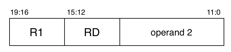
Bits 19:16 encode the first register operand (the bits interpreted as a 4-bit natural number) and bits 15:12 the destination register. Bits 11:0 are the second operand, and this can either be an immediate value (bit 25 is 1), or a second register operand (bit 25 is 0). But there are too few bits for immediate values if treated just as natural numbers or integers, and there are too many bits to specify a register. So both possibilities have more complicated descriptions.
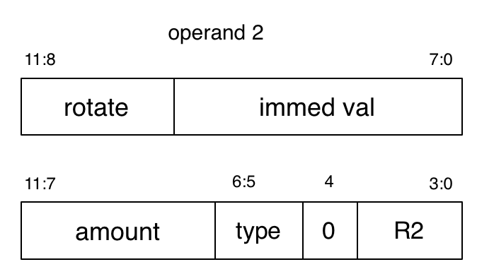
For a second operand which is an immediate value, bits 7:0 are rotated right by an amount specified by bits 11:8. Rotating right by one moves bit \(i\) to bit \(i-1\), and bit 0 to bit 31. Four bits can specify sixteen values, and there are thirty-two possible rotation amounts, so bits 11:8 are treated as a natural number and multiplied by two to get the rotation amount. Of course, we can still only specify 4096 bit patterns this way, but this allows bit patterns that involve more significant bits as well as less significant bits. We specify such an operand in assembly language by the Racket constant that is its result, such as #xFF000000 (which is #xFF rotated right by four, or #x4). The assembler should signal an error if the programmer attempts to use a 32-bit immediate value that cannot be created in this fashion.
For a second register operand, bits 3:0 specify the register, and bits 11:4 specify various kinds of shifts and rotates. A logical shift left by one position moves bit \(i\) to bit \(i+1\), and sets bit 0 to 0. This happens on the value taken from the register, not on the value stored in the register (that does not change). A shift right is like a rotate right, but bit 31 is set to 0 instead of bit 1 being moved to it. However, sometimes with a shift right we do not want to set the high-order bits to 0.
Suppose the register contains a bit pattern we want to interpret as a two’s complement number. Shifting such a number one position left, putting a 0 into the least significant bit, is multiplication by 2 (assuming the resulting number fits into 32 bits). Shifting right, putting a 0 into the most significant bit, would be division by 2 for positive numbers, but for a negative number, we would want to set bit 31 to 1 instead of 0, otherwise a negative number shifted would become a positive number. The resulting arithmetic shift right by one position is division by 2, rounding towards negative infinity. So we now have logical shift left, logical shift right, arithmetic shift right, and rotate right. These four possibilities are coded as 00, 01, 10, and 11 respectively in bits 6:5. Why are there only four possibilities instead of six? Arithmetic shift left is the same as logical shift left, and each rotate left has a corresponding rotate right with the same effect.
Back to bits 11:4, specifying various kinds of shifts and rotates on the value taken from the register specified by bits 3:0. If bit 4 is 0, bits 11:7 interpreted as a natural number specify a shift/rotate amount. What if bit 4 is 1? In ARM assembly, this has a further interpretation, but for the sake of simplicity I’ll omit it here. To specify a second register operand in assembler, we write the register name, followed by one of the codes lsl, lsr, asr, ror, followed by the shift amount as a Racket constant.
As an example, (add r0 r0 r0 lsl 1) has the effect of multiplying r0 by 3.
Some of the other data processing operations include sub, rsb (reverse subtract, so shifts and rotates can be applied to either operand). There are logical operations such as and, orr, eor (exclusive-OR), all of which are done bitwise. There is a mov operation, and mvn, which is bitwise logical NOT, but is called "move not" because, as we saw in Part I, negating a two’s complement number is applying logical NOT to all bits and adding 1, so this operation can be used to load registers with negative immediate operands. (mvn r0 0) will put -1 into r0.
There are versions of some of these instructions that do not have destinations, but perform the operation on the operands and use it to set status bits. (cmp r0 r1) subtracts r1 from r2 and throws away the result. But a subsequent instruction with a eq prefix will succeed if and only if the subtraction yielded zero. teq does bitwise exclusive-OR (unlike cmp, it does not affect the carry bit) and tst does bitwise AND.
Conversely, we may wish to perform an operation such as add and affect the destination register but not the status bits. In fact, this is the default. The s suffix (after the other suffixes) is used to indicate that the status bits are affected.
Combining these operations with conditional execution of other instructions allows the FIST programmer to often avoid the conditional branching that we saw with PRIMP. Consider the task of setting r1 to the sign (1 or -1) of r0. We might phrase this in pseudo-SIMP as:
(set r1 0) |
(iif (> r0 0) (set r1 1) (set r1 -1) |
Using our earlier techniques for compiling SIMP to PRIMP, this would get compiled into code using conditional branches. But here is the code in FIST. (The mvnmi instruction moves -1, if it is executed.)
| (mov r1 0) |
| (teq r0 0) |
| (mvnmi r1 0) |
| (movpl r1 1) |
5.2.3 Software interrupt instructions
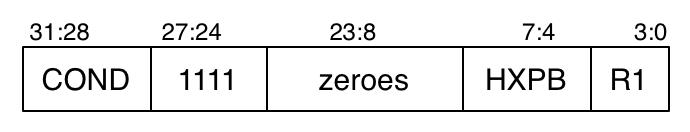
The swi "software interrupt" instruction lets the operating system perform various functions. In the ARM system, the effect of this instruction is dependent on the system running; the hardware only facilitates a subroutine call to something that handles the interrupt. This instruction is used to deal with I/O and other exceptional situations. Here is the encoding:
Since we are working with a simulator, we can use this instruction for things that are convenient to us, like integer output, integer input, and stopping the program:
| (swi print r1) |
| (swi read r2) |
| (swi halt) |
For print and read, we can use the c suffix to indicate character I/O, and for print, the x suffix to indicate hexadecimal output (good for debugging).
5.2.4 Branch instructions
The unconditional branch instruction b, like every other instruction, can be executed conditionally, which gives us conditional branching. Here is the encoding:
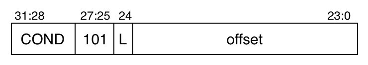
The only variation here is that the L bit indicates the use of the link register (r14) to store old value of PC when the branch occurs. This allows for fast calling of leaf subroutines (those that do not call other subroutines), avoiding the overhead necessary to store the PC on the stack. I will discuss the more general mechanism below.
As an example of a nontrivial computational task, consider the goal of computing and printing the GCD of a and b using only subtraction and comparisons. This relies on the identity \(\textit{gcd}(a,b) = \textit{gcd}(a-b,b)\) when \(a>b\). Of course, \(\textit{gcd}(a,a) = a\), and we can apply a similar identity in the remaining case. This is not an efficient algorithm if one number is much smaller than the other, but it does work.
We’ll look at SIMP, PRIMP, and FIST programs that use this idea to compute the GCD, starting with SIMP.
| (seq |
| (while (not (= a b)) |
| (seq |
| (iif (> a b) |
| (set a (- a b)) |
| (set b (- b a))))) |
| (print a)) |
The PRIMP program is a direct translation using the techniques discussed in the previous lecture module.
| (label gcd) |
| (eq tmp a b) |
| (branch tmp end) |
| (lt tmp a b) |
| (branch tmp less) |
| (sub a a b) |
| (jmp gcd) |
| (label less) |
| (sub b b a) |
| (jmp gcd) |
| (label end) |
| (print a) |
But the FIST program is shorter and clearer. This is somewhat of a poster child for the FIST architecture. Note we are using labels and pseudo-instructions as we did for PRIMP.
| (label gcd) |
| (cmp r0 r1) |
| (subgt r0 r0 r1) |
| (suble r1 r1 r0) |
| (bne gcd) |
| (swi print r0) |
The cmp at the top of the loop sets the status bits, and the subgt is executed if r0 is greater than r1. Whether it is executed or not, the status bits are not affected, because there is no s suffix on subgt. So the suble is executed if r0 was less than r1 originally, and it also does not affect the status bits. The bne thus branches back to the top of the loop if one of the subtractions takes place, and if it does not, the two registers contain the same value, which is the GCD.
Here is an example of a loop with a fixed decrement, used in the task of adding up the numbers from 100 down to 1.
| (mov r0,0) ; r0 holds sum |
| (mov r1,100) ; r1 holds i |
| (label loop) |
| (add r0,r0,r1) |
| (sub r1,r1,1) |
| (cmp r1,0) |
| (bne loop) |
| (swi print r0) |
5.2.5 Data transfer instructions
The data transfer instructions are ldr for load register and str for store register. For example, (ldr r0 (r1)) copies the word whose address is in r1 from memory into r0.
These resemble PRIMP’s load-index and store-index instructions, but the address calculations can be more complex. Here is the encoding.
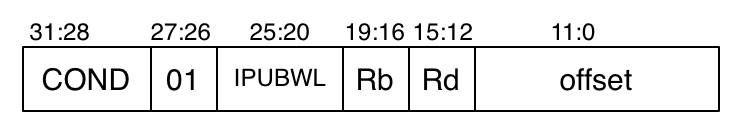
Rd is the source/destination register. Rb is the base register, used in the calculation of the memory address. Bits 25:20 are the six IPUBWL selector bits, similar to the data operation opcode. But in this case, every bit has a specific meaning, with an appropriate one-letter mnemonic (and different ways of indicating its setting in an assembly-language instruction).
The L bit indicates whether the instruction is load (from memory) or store (to memory), and this is indicated by the first three letters of the instruction. The B bit indicates whether a word or byte is being transferred, the latter being indicated in assembly language by a b suffix on the instruction name, e.g. (ldrb r0 (r1)).
The I bit indicates immediate offset or register offset. 1 means the 12-bit offset field is regarded as a 12-bit natural number. 0 means that register offset (as with data instructions) is used. Refer to the data instructions section for the messy details. Here are two examples of an immediate offset and register offset.
(ldrb r0 (r1 16))
(str r0 (r1 r2 lsl 2))
This last instruction works nicely if r1 contains the address of an array of words and r2 contains an index into it.
The U bit indicates up/down, that is, whether the offset is added or subtracted. The latter is indicated in assembly language by a negative sign on the offset amount or register. The P bit indicates pre-indexing or post-indexing. Pre-indexing is what we’re used to, where the offset is added before the transfer is made. In post-indexing, the offset is added after the transfer is made.
Post-indexing only makes sense with writeback, where the memory address computed is written back into the base register Rb. The W bit indicates whether or not writeback takes place. In the assembly language, pre-indexed writeback is indicated by an exclamation mark after the offset. Post-indexed writeback is required.
(ldr r0 (r1 4 !)) (pre)
(ldr r0 (r1) 4) (post)
Writeback lets us step through memory with a fixed offset (good for arrays of items of various sizes, such as string, integer, structs). To illustrate this, let’s consider the task of copying an array of 100 integers (each fitting into one word). Assume r0 points to the destination and r1 to the source.
This code uses an index in r2 counting up from zero, and no writeback. The values of r0 and r1 do not change.
| (mov r2 0) |
| (label loop) |
| (ldr r3 (r1 r2 lsl 2)) |
| (str r3 (r0 r2 lsl 2)) |
| (add r2 r2 1) |
| (cmp r2 r2 100) |
| (blt loop) |
This code uses an index counting down from 100. r2 is used as a counter and is not involved in index/offset computations; instead, writeback is used to "move the pointers" r0 and r1.
| (mov r2 100) |
| (label loop) |
| (ldr r3 (r1) 4) |
| (str r3 (r0) 4) |
| (subs r2 r2 1) |
| (bne loop) |
5.2.6 Block data transfer instructions
The ldm and stm instructions transfer information between a set of registers and consecutive locations of memory. One important use is for stack frame operations. Here is the encoding.
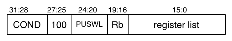
The base register contains the address in memory that is the source/destination of the block of information. We will explain the effect of executing these instructions using r13 (also called sp) as a stack pointer even though other base registers and other uses are possible.
With a stack, we have some choices. Increment stack pointer on push, or decrement? Do so before data transfer, or after?
Suffix i or d determines increment/decrement Suffix b or a determines before/after. These determine U (up/down) and P (pre/post) bits in the encoding. For example, a descending stack (growing towards higher-numbered memory) whose stack pointer points to the first empty position is what we typically have been using in this flânerie. This uses post-up addressing. (Alternately, in ARM assembler, a different set of suffixes indicating descending/ascending and empty/full can be used, but I have not included this in FIST.)
Writeback is indicated by ! after the base register (done for push/pop, not for peek). The register list can be in any order in the assembly-language instruction, but different orders result in the same bit pattern in bits 15:0 indicating which registers are involved. The registers are written in increasing numerical order of their names when the instruction is executed (so if r15 is in the register set, it is written last) but the lowest-numbered register is written to or taken from the lowest memory address.
Here are two sequences of instructions that have the same effect, pushing four registers onto the stack. Note how the range r1-r3 is indicated.
| (str r1 (sp) 4) |
| (str r2 (sp) 4) |
| (str r3 (sp) 4) |
| (str r5 (sp) 4) |
| (stmia sp ! ((r1 r3) r5)) |
The reverse operation, popping four values off the stack into these four registers, is (ldmdb sp ! ((r1 r3) r5)). Note that to "undo" the effect of a multiple data transfer instruction, we execute an instruction where ascending/descending and before/after are switched.
Here is one more example of the array copying task, using multiple data transfer instructions to move only one register at a time, but taking advantage of the automatic updating of the base register to move the two pointers in r0 and r1.
| (add r2 r0 100) |
| (label loop) |
| (ldmia r1 ! (r3)) |
| (stmia r0 ! (r3)) |
| (cmp r2 r0) |
| (bne loop) |
By using more registers, the copying can be done in larger chunks. Since the running time of a multiple data transfer increases linearly with the number of bytes transferred, this does not really save any time in the actual copying, but it does require less overhead for the loop operations.
5.3 Towards a FIST simulator
We can extend the framework of the PRIMP simulator to create a FIST simulator.
Memory
Registers
Program counter
Halted? flag
The implementation of FIST instructions is quite similar to what we did for PRIMP. But dispatching of instructions is more complicated. We must decode the integer representing an instruction into something resembling the PRIMP format (at least as far as the arguments of the instruction are concerned).
But instead of symbolic instruction names as PRIMP has, we have numeric opcodes. We set up dispatch tables mapping opcodes to actions. Since the opcodes are numbers, we can use a vector.
| (define immediate-instructions |
| (vector |
| bad jmpi jsr bez bnez |
| blz blez bgz bgez ldi)) |
To use a dispatch table:
| (define (dispatch-instruction t m op d) |
| ((vector-ref t op) m d)) |
Most of the rest of the details are very similar to the PRIMP simulator.
The simulator does not address the major time difference between register-register and memory-register instructions. This, after all, was the major reason to introduce registers. In practice, this time difference affects both hardware and software design. Processors might stall if an instruction requires the use of a value from memory that has not arrived in a register yet, or they might try to execute later instructions that do not depend on that value. Compilers, depending on the capabilities offered by the hardware, may try to arrange instructions to improve execution time. These issues are complicated and largely beyond the scope of this flânerie; they are discussed in textbooks on computer architecture.
Many of the ideas we developed for programming in PRIMP also carry over to FIST code. For functions or subroutines, we need to standardize conventions between calling code and called code. Which registers are used for communication, which for working, which should not be overwritten by called code? Typically the stack pointer is kept in a dedicated register. There is also usually a register dedicated to the return value.
The FIST assembler can use the same pseudo-instructions as PRIMP. But most of the work in the PRIMP assembler involved resolving symbolic labels. The FIST assembler also has to encode each instruction into 32 bits. Details are left as an exercise.
5.4 Towards a SIMP to FIST compiler
All of the techniques used for the SIMP to A-PRIMP compiler are relevant for a SIMP to FIST compiler, but there are additional complications. I will just discuss some high-level issues here.
One issue is the size of numbers. SIMP uses unbounded numbers, but the FIST memory stores fixed-sized words. There are a number of ways to deal with this issue. The Racket-style solution would be to develop a FIST implemention of "bignums", or unbounded numbers. These are best stored as arrays of "big digits", each of which will fit into one word. There is some discussion of this (with references) at the end of assignment question C10 in the C learning materials.
The C-style solution (also used in Java and most other imperative languages) would be to use "fixnums", that is, numbers of restricted size (typically fitting into a single word of memory). We can restrict SIMP to only use bounded numbers. What happens when a SIMP operation produces a number that will not fit into a single word? Do we raise an error and stop the simulation? That seems harsh. But if we want to give the programmer a chance to recover from an overflow error, we must extend the language in some fashion. Most imperative language implementations ignore overflow (again for performance reasons).
Arithmetic overflow is possible with the addition of two very large numbers, but with multiplication, the numbers need only be of modest size. The addition of two 32 numbers produces at most a 33-bit result (the extra bit being the carry bit), but the multiplication of two 32-bit numbers can produce a 64-bit result. Current ARM architectures, and others, can use two registers (or one double-width register) to hold the result of integer multiplication.
Another issue is that SIMP supports string constants, and FIST does not. A 32-bit architecture can fit four characters into a word using the 7-bit ASCII representation; extended character sets such as Unicode cannot be packed as densely. Using a fixed-width character representation, strings can be then represented as arrays of characters. This is the actual representation in both Racket and C, though the details differ between the two languages.
A more complicated issue stems from the fact that it is faster to use registers than memory locations. We would naturally want FIST programs that our compiler produces to be as efficient as possible. As with hand-written FIST programs, we must decide which registers are reserved for specific uses (e.g. stack pointer, return value) and which ones are generally available. It is faster to use registers for variables and intermediate results, but we may run out of registers, and have to spill some of these into memory locations as necessary. The tradeoffs between the various uses of the limited set of registers are not straightforward. Optimizing the number of temporary locations used also becomes more important.
These issues are discussed at length in textbooks on compilers.
In the next lecture module, we will focus on Racket and Racket-like languages (such as Faux Racket, which we used in Part I). We will discuss how some aspects of the operation of DrRacket can be explained using the memory model, and how we might implement an efficient Racket interpreter.
Exercise 18: Here are a couple of helper functions whose implementation will get you used to dealing with bits of words in Racket. The bitwise operations provided by Racket (section 4.2.2.6 of the Racket Reference) will be helpful, though you can implement all of them with integer arithmetic operations. However, Racket’s bitwise operations work on unbounded values, whereas for FIST purposes, we need to work with bitfields of various sizes (such as 32 bits, which is a word). To that end, we define a k-bits as a Racket value between 0 and \(2^k-1\) inclusive.
Write the following functions.
| ; bits-to-2c-word: (m+1)-bits nat -> word |
| ; to-imm-offset: word -> (union (list 4-bits 8-bits) #f) |
bits-to-2c-word consumes an (m+1)-bits bf and the value of m, and produces a 32-bits or word that is the result of interpreting bf as an (m+1)-bit two’s complement integer and extending it to a 32-bit two’s complement integer. So, for example, #b110, considered as a 3-bit two’s complement integer, is -2, so applying bits-to-2c-word to #b110 would give #xFFFFFFFE. But changing the first argument to #b010 would give #x00000002.
to-imm-offset consumes a word and produces a two-element list containing the values of the fields (rotate and amount) that would be needed to generate the word as an immediate offset (bits 11:0) for a FIST data processing instruction, or #f if this is impossible. If a choice of rotation amount is possible, produce the smallest amount. \(\blacksquare\)
Exercise 19: Write the function decode that consumes a 32-bit word and produces the S-expression FIST assembly language representation of the instruction encoded in that word. For example, (decode #xE0834002) should evaluate to '(add r4 r3 r2). The complete format is described in the FIST instruction set summary just below. Do not use sp, lr, or pc; stick to r0 through r15. In the case of a multiple data instruction, give the register list in increasing order, and reduce its size by replacing three or more consecutive registers by a range. If the word does not decode to an instruction, raise an error.
It is possible to write this function using one giant deeply-nested cond. Please do not do this. Write lots of short helper functions with meaningful names so that your code is readable and matches the logic of the instruction summary. If you find yourself repeating similar bits of code, cutting and pasting and changing a small amount, try to generalize and split that code out into a helper function. Sometimes it is good to use a helper function even if it is only used once in the rest of the code, just to improve clarity. Use vectors to map small integers to relevant strings or symbols as described in the lecture notes. Quasiquote, unquote, and unquote-splicing can help to make code clearer, but don’t overuse them; cons, list, and append are also useful. You will have choices at points among using symbols, strings, or lists of characters; choose carefully to avoid excessive conversion back and forth. \(\blacksquare\)
Exercise 20: Write the function encode that does the opposite of what decode does in the previous exercise. \(\blacksquare\)
The next three exercises are more like suggestions for projects. I never assigned them as homework in the course I taught based on this material, because I had to balance this material against other parts of the course, and also be mindful of the other courses making demands on my students at the same time. But some students chose to do some of this work voluntarily.
Exercise 21: Implement a FIST simulator. \(\blacksquare\)
Exercise 22: Implement a FIST assembler, using the ideas from A-PRIMP to define A-FIST. \(\blacksquare\)
Exercise 23: Complete the toolchain by implementing a SIMP-to-A-FIST compiler. \(\blacksquare\)
5.5 Summary of the FIST architecture
This section summarizes the FIST instruction set in sufficient detail to do encoding and decoding. More details are needed in places to specify the full effect of some instructions. You can fill those in at your convenience if you want to write a FIST simulator. Some of the information below is repeated from above, and some is new.
In the FIST architecture, there are 16 registers. The registers are called r0 through r15. r15 or pc is the program counter; r14 or lr is the link register (see the bl instruction); r13 or sp is the stack pointer (by convention).
Bits 1:0 of the PC are always 00. Bits 31:28 of the PC are the status bits, ignored while fetching the next instruction to be executed, but possibly affecting or affected by the execution of the instruction. In order from most significant, they are N (negative), Z (zero), C (carry), and V (overflow).
Each instruction is exactly one word long and has a basic name in the assembly language that is usually three letters long (such as add). Each instruction can be executed conditionally, with the condition indicated by a condition code in bits 31:28 of the encoded instruction and by a two-letter suffix on the instruction name in the assembly language (indicated as "<cond>" in the instruction descriptions below).
Code |
| Suffix |
| Description |
| Flags |
0000 |
| eq |
| Equal/zero |
| Z=1 |
0001 |
| ne |
| Not equal |
| Z=0 |
0010 |
| cs |
| Carry set |
| C=1 |
0011 |
| cc |
| Carry clear |
| C=0 |
0100 |
| mi |
| Minus/negative |
| N=1 |
0101 |
| pl |
| Plus / positive or zero |
| N=0 |
0110 |
| vs |
| Overflow |
| V=1 |
0111 |
| vc |
| No overflow |
| V=0 |
1000 |
| hi |
| Unsigned higher |
| C=1,Z=0 |
1001 |
| ls |
| Unsigned lower or same |
| C=0 or Z=1 |
1010 |
| ge |
| Signed greater than or equal |
| N=V |
1011 |
| lt |
| Signed less than |
| not N=V |
1100 |
| gt |
| Signed greater than |
| Z=0 and N=V |
1101 |
| le |
| Signed less than or equal |
| Z=1 or not N=V |
1110 |
| al |
| Always (default) |
| any |
1111 |
| nv |
| Never |
| none |
5.5.1 Data processing instructions
opcode |
| name |
| effect |
0000 |
| and |
| Rd:= Op1 AND Op2 |
0001 |
| eor |
| Rd:= Op1 EOR Op2 |
0010 |
| sub |
| Rd:= Op1 - Op2 |
0011 |
| rsb |
| Rd:= Op2 - Op1 |
0100 |
| add |
| Rd:= Op1 + Op2 |
0101 |
| adc |
| Rd:= Op1 + Op2 + C |
0110 |
| sbc |
| Rd:= Op1 - Op2 + C - 1 |
0111 |
| rsc |
| Rd:= Op2 - Op1 + C - 1 |
1000 |
| tst |
| set status bits on Op1 AND Op2 |
1001 |
| teq |
| set status bits on Op1 EOR Op2 |
1010 |
| cmp |
| set status bits on Op1 - Op2 |
1011 |
| cmn |
| set status bits on Op1 + Op2 |
1100 |
| orr |
| Rd:= Op1 OR Op2 |
1101 |
| mov |
| Rd:= Op2 |
1110 |
| bic |
| Rd:= Op1 AND NOT Op2 |
1111 |
| mvn |
| Rd:= NOT Op2 |
I: Immediate (1) / register (0)
S: Status bits affected (1) / not (0)
Immediate mode: bits 7:0 are rotated right by an amount specified by bits 11:8 interpreted as a natural number and multiplied by 2.
Register mode:
type |
| meaning |
00 |
| logical left |
01 |
| logical right |
10 |
| arithmetic right |
11 |
| rotate right |
The amount is interpreted as a natural number.
Assembly-language formats (<angle brackets> indicate optional parts, with <> removed):
mov, mvn: (name<cond><s> Rd Op2)
Here and in what follows, cond indicates the two-letter condition code suffix (if omitted, al is assumed, so need never be written), and the s suffix indicates whether the status bits are affected or not.
cmp, cmn, teq, tst:
(name<cond> R1 Op2)
(the S bit is set in the encoding but no s suffix is used)
Others: (name<cond><s> Rd R1 Op2)
Operand 2 format: <number> or R2 <shift> where shift is omitted if the shift amount is zero, otherwise it is shiftname number and shiftname is one of lsl, lsr, asr, ror.
5.5.2 Software interrupt instructions
The bits HXPB have the following meanings:
H: Halt (1) / other (0)
X: Hex (1) / normal (0, prints as number or character)
P: Print (1) /read (0)
B: Byte (1) /word (0)
Assembly-language format:
(swi<cond> name<b><x> <R1>) where
name is one of print, read, halt.
The b suffix can only be applied to print or read,
and the x suffix can only be applied to print.
No register is specified for halt.
5.5.3 Branch instructions
L=1: store PC in r14.
The offset is interpreted as a 24-bit two’s complement integer and added to the PC.
Assembly-language format:
(b<l><cond> offset)
5.5.4 Data transfer instructions
L: load (1) / store (0)
W: writeback (1) / no writeback (0)
B: byte (1) / word (0)
U: up (1, offset added) / down (0, offset subtracted)
P: pre-indexing (1) / post-indexing (0)
I: immediate (1) / register (0)
In immediate mode, the offset field is treated as a natural number and added to / subtracted from the value in the base register to determine the memory address for the transfer (to the destination register for load, from it for store). In register mode, bits 3:0 define a register from which the offset amount is taken, shifted according to bits 11:4 interpreted as in register mode for data processing instructions (however, R must be 0).
With pre-indexing, the offset is used before the transfer; with post-indexing, it is used after the transfer, which makes sense with writeback (the computed memory address is written back into the base register). For post-indexing, writeback is mandatory and W must be zero; for pre-indexing, it is optional.
Assembly-language format:
For pre-indexing: (name<cond><b> Rd (Rb <-> <Op2> <!>)) where name is one of ldr or str, and Op2 is described for data processing instructions (omitted if zero). A negative sign on a numerical immediate offset (like -7) or by itself before the name of a third register (like - r3) is used to indicate that the offset should be subtracted. The exclamation mark indicates writeback.
For post-indexing: (name<cond><b> Rd (Rb) <-> <Op2>).
5.5.5 Block data transfer instructions
L: load (1) / store (0)
W: writeback (1) / no writeback (0)
S: set status bits if PC written to (1) / don’t (0)
U: up (1, offset added) / down (0, offset subtracted)
P: pre-indexing (1) / post-indexing (0)
The base register contains the address in memory that is the source/destination of the block of information. A 1 in bit i indicates that register ri is in the register set, otherwise it is not. The register set is written to (for load) or read from (for store) in increasing numerical order of i, and consecutive memory locations are used (that is, the offset is 4) for the source (for load) or destination (for store).
Assembly-language format:
(name<cond><i/d><b/a> Rb <!> (Rlist)) where
name is one of ldm or stm;
suffix i or d (one must be included)
determines increment (offset added) / decrement (offset subtracted);
suffix b or a (one must be included)
determines before (pre-indexing) / after (post-indexing);
the exclamation mark indicates writeback;
Rlist is ri ... and can be in any order, and
ranges can be indicated in Rlist by (ri rj).