Back to Contents Page
Installing Drives: Dell™ PowerEdge™ 8450 Systems
Installation and Troubleshooting Guide
Overview • Removing the Peripherals Bay • Installing an IDE CD-ROM Drive • Connecting an External SCSI Tape Drive
• Installing SCSI Hard-Disk Drives
• Installing a Dell Host Adapter Card
• Configuring the Boot Device
Overview
Your computer features a removable peripherals bay that incorporates four drive bays
for installing the following types of drives:
- The two externally accessible drive bays hold a user-accessible,
half-height, 5.25-inch device (typically an integrated drive electronics [IDE] CD-ROM
drive) and a standard 3.5-inch diskette drive, which is controlled by the diskette drive
controller on the system board.
- The hard-disk drive bays can hold one or two 1-inch small computer
system interface (SCSI) hard-disk drives.
See Figure 1 for a general view of the various drives, connector cables, and power
cables in the peripherals bay.
Figure 1. Peripherals Bay
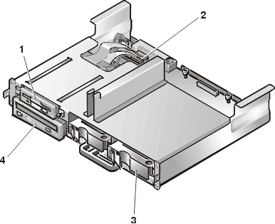
1
|
Diskette drive |
2
|
SCSI backplane board |
3
|
Hard-disk drive carrier |
4
|
IDE CD-ROM drive |
The following subsections describe how to install these types of
drives.
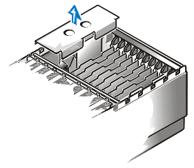
Removing the Peripherals
Bay
To remove the peripherals bay from the computer, perform the
following steps.
 |
WARNING: Before installing the IDE
CD-ROM drive, you must turn off the computer and disconnect it from the electrical outlet.
For more information, refer to Safety
First—For You and Your Computer. |
- Turn off the system, including any attached peripherals, and
disconnect the system from its electrical outlet.
- Remove the front bezel.
- Loosen the four captive screws securing the memory board cover to the
front of the system chassis, then remove the cover (see Figure 2).
Figure 2. Removing the Peripherals Bay
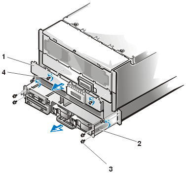
1
|
Memory board cover |
2
|
Peripherals bay |
3
|
Peripherals bay screws (4) |
4
|
Memory-board cover retention
screws (4) |
- Remove the four screws securing the peripheral bay to the system
chassis.
- Slide the peripherals bay out of the system chassis.
Installing an IDE-CD
ROM Drive
To install an IDE CD-ROM drive, perform the following steps.
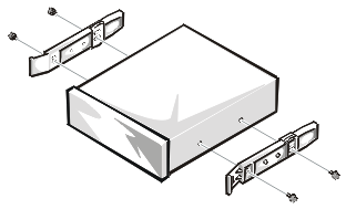
- If the drive does not already have drive rails attached, attach a
drive rail to each side of the drive. Orient the drive rails as shown in Figure 3. Secure
each drive rail to the drive with a screw in each of the lower slotted screw holes on the
drive rail.
Figure 3. Attaching Drive Rails
- Remove the peripherals bay.
- Slide the new drive into its bay until it snaps securely into place.
If necessary, you can adjust drive alignment by repositioning one or both rails.
- Connect the interface cable connector on the IDE-drive interface
cable to the IDE-drive interface cable connector on the SCSI backplane board. See Figure
4.
Figure 4. IDE Interface Connector on the SCSI Backplane Board
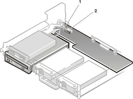
1
|
IDE interface cable connector |
2
|
Diskette-drive interface
cable connector |
- Connect the DC power cable connector to the drive.
Figure 5 shows the four-pin power input connector on the drive.The power connectors are
keyed to avoid incorrect insertion; do not force two connectors together if they do not
fit properly.
Figure 5. Power Input Connector
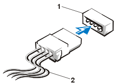
1
|
Power input connector |
2
|
DC power-cable connector |
- Slide the peripheral bay back into the system chassis and lock it in
place with the two retention levers.
- Replace the memory board cover and secure it using the four captive
screws.
- Replace the front bezel.
- Replace the computer cover, reconnect the system to the electrical
outlet, and turn on the system.
- Run the IDE Devices
test in the Dell Diagnostics to confirm that the new drive works correctly.
Connecting an
External SCSI Tape Drive
This subsection describes how to configure and install an external SCSI tape drive.
SCSI Configuration Information
Although SCSI devices are installed essentially the same way as
other devices, their configuration requirements are different. Before you connect an
external SCSI tape drive, refer to the guidelines in the following subsections.
SCSI ID Numbers
Each device attached to a SCSI host adapter must have a unique SCSI
ID number from 0 to 7.
When SCSI devices are shipped from Dell, the default SCSI ID
numbers are assigned as follows:
- The integrated Ultra/Narrow SCSI host adapter is configured through
the basic input/output system (BIOS) as SCSI ID 7.
- A SCSI tape drive is configured as SCSI ID 6 (the default ID number
for a tape drive).
 |
NOTE: You do not need to assign SCSI
ID numbers sequentially, or attach SCSI devices to a SCSI interface cable in order by ID
number. |
Device Termination
When you attach external SCSI devices, use only external SCSI cables
with active termination on the cable, and disable termination on all the external SCSI
devices. For information on disabling termination on the device, see the documentation
provided with any optional SCSI device you purchase.
Installing the Tape Drive
To connect a stand-alone SCSI tape drive, perform the following
steps:
- Prepare the tape drive for installation.
- Ground yourself by touching an unpainted metal surface on the back of
the computer.
- Unpack the tape drive (and controller card, if applicable), and
configure the tape drive for the system according to the documentation that came with the
tape drive.
- If the tape drive was supplied with a controller card, perform the
following steps to install the card:
- Remove
the computer cover.
- Install the controller
card in an expansion slot.
- Replace the computer cover.
- Connect the tape drive's interface/DC power cable to the external SCSI connector on the back of the system, or the
connector on the controller card supplied with the tape drive.
- Secure the connection by tightening the screws on the connector.
- Reconnect the computer and peripherals to electrical outlets, and
turn them on.
- Perform a tape backup and verification test with the drive as
instructed in the software documentation that came with the drive.
Installing SCSI
Hard-Disk Drives
This subsection describes how to install and configure SCSI hard-disk drives in the
computer's internal hard-disk drive bays, and how to upgrade the system by installing a
Dell host adapter card.
The internal hard-disk drive bays provide space for one or two
1-inch hard-disk drives. These drives connect to a SCSI backplane board. An Ultra2/low
voltage differential (LVD) SCSI cable connects the SCSI backplane board to the Ultra2/LVD
SCSI host adapter connector on the input/output (I/O) board or to an optional SCSI host
adapter card such as the Dell PowerEdge Expandable RAID Controller host adapter card.
Before You Begin
Dell PowerEdge 8450 systems with a PowerEdge Expandable RAID Controller host adapter
card installed support hot-pluggable drive installation and removal. Before attempting to
remove or install a drive while the system is running, see the documentation for the Dell
PowerEdge Expandable RAID Controller to ensure that the SCSI host adapter is configured
correctly to support hot-pluggable drive removal and insertion.
SCSI hard-disk drives are supplied by Dell in special drive carriers
that fit in the hard-disk drive bays.
|
NOTES: For maximum performance,
install Ultra2/LVD drives exclusively. Although you can install a combination of
Ultra2/LVD and Ultra hard-disk drives, they will operate at the slower Ultra transfer
rate. Dell recommends that you use only drives
that Dell has tested and approved for use with the SCSI backplane board. |
Refer to the following guidelines when you configure the SCSI drive:
- Disable termination on the drive. The SCSI backplane board provides
termination for the SCSI bus.
- Set the SCSI ID on all drives to 0. All SCSI ID numbers for the
drives are set by the SCSI backplane board.
- Configure the drive so that the drive motor waits for a Start Unit
command from the SCSI host adapter before spinning.
You may need to use different programs than those provided with the
operating system to partition and format SCSI hard-disk drives. See "Installing and
Configuring SCSI Drivers," in the User's Guide for information and
instructions.
 |
CAUTION: Do not turn off or reboot
your system while the drive is being formatted. Doing so can cause a drive failure. |
When you format a high-capacity SCSI hard-disk drive, allow enough
time for the formatting to be completed. Long format times for these drives are normal. A
9-gigabyte (GB) hard-disk drive, for example, can take up to 2.5 hours to format.
Installing a SCSI Hard-Disk Drive
To install a SCSI hard-disk drive, perform the following steps.
|
CAUTION: Hot-pluggable drive
installation is not supported for systems without a Dell PowerEdge Expandable RAID
Controller host adapter card. |
- Power down the hard-disk drive bay. If the system does not have a
PowerEdge Expandable RAID Controller installed, shut down the system.
- Remove the front bezel.
- Open the hard-disk drive carrier handle (see Figure 6).
Figure 6. Installing a SCSI Hard-Disk Drive Carrier
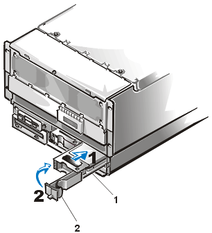
1
|
hard-disk drive carrier |
2
|
hard-disk drive carrier
handle |
- Insert the carrier into the drive bay (see step 1 in Figure 6).
- Close the drive carrier handle to lock the drive in place (see step 2
in Figure 6).
- Replace the front bezel.
- Lock the keylock.
- Install any required SCSI device drivers.
See "Installing and Configuring SCSI Drivers," in the User's Guide for
information.
- If the hard-disk drive is a new drive, run the Symbios SCSI Controllers test in the
Dell Diagnostics.
Removing a SCSI Hard-Disk Drive
To remove a SCSI hard-disk drive, perform the following steps.
|
CAUTION: Hot-pluggable drive removal
is not supported for systems without a Dell PowerEdge Expandable RAID Controller host
adapter card. |
- If the system does not have a PowerEdge Expandable RAID Controller
installed, shut down the system.
- For systems with PowerEdge Expandable RAID Controllers, power down
the hard-disk drive bay and wait until the SCSI hard-disk drive indicator codes
on the drive carrier signal that the drive may be removed safely. If
the drive has been online, the drive status indicators will flash sequentially as the
drive is powered down. When all indicators are turned off, the drive is ready for removal.
- Remove the front bezel.
- Open the drive carrier handle to release the carrier.
- Slide the carrier toward you until it is free of the drive bay.
- Replace the front bezel.
Installing a Dell
Host Adapter Card
Follow these general guidelines when installing a Dell host adapter
card. For specific instructions, refer to the documentation supplied with the host adapter
card.
|
WARNING: Before installing the host
adapter card, you must turn off the computer and disconnect it from the electrical outlet.
For more information, refer to Safety
First—For You and Your Computer. |
- Unpack the host adapter card, and prepare it for installation.
Refer to the documentation accompanying the host adapter card.
- Remove
the computer cover.
- Remove the input/output (I/O) riser board cover from the chassis (see
Figure 7).
Figure 7. Removing the I/O Riser Board Cover
- Detach the Ultra2/LVD SCSI interface cable from the primary SCSI
host-adapter connector on the I/O board (see Figure 1 in
"Installing System Options" for the location of the SCSI host adapter
connector).
- Install the host
adapter card .
If you are installing a Dell PowerEdge RAID Controller 2/SC, install the card in
Peripheral Component Interconnect (PCI) expansion slot 1.
- Connect the end of the Ultra2/LVD SCSI interface cable to the
connector on the host adapter card.
To identify the correct connector, refer to documentation for the host adapter card.
- Attach the external SCSI devices to the SCSI host adapter card's
external connector on the computer's back panel.
If you are attaching multiple external SCSI devices, daisy-chain the devices to each other
by using the cables shipped with each device.
- Replace the I/O riser board cover (see Figure 7).
- Replace the computer cover, and reconnect the computer and
peripherals to electrical outlets.
- Connect the external device(s) to electrical outlet(s).
For each external device, plug the socket end of the power cable into the power receptacle
on the back of the device. Plug the other end of the power cable into an electrical
outlet.
- Install any required SCSI device drivers.
See "Installing and Configuring SCSI Drivers," in the User's Guide for
information and instructions.
- Test the SCSI devices.
Test a SCSI hard-disk drive by running the Symbios SCSI Controllers test in the
Dell Diagnostics. To test a SCSI tape drive, also refer to the documentation for the tape
drive software to perform a tape drive backup and verification test.
Configuring the Boot
Device
If you plan to boot the system from a hard-disk drive, the drive
must be attached to the primary (or boot) controller or SCSI host adapter card. The device
that the system boots from is determined by the boot order specified in the system setup
program.
The system setup program provides options that the system
uses to scan for installed boot devices. Refer to the User's Guide for information
about the system setup program.
Back to Contents Page