Back to Contents Page

Troubleshooting Your System

Dell™ PowerEdge™ 4600 Systems Installation and Troubleshooting Guide

  Safety First—For You and Your System

  External Connections

  Checking Specific System Problems

  Start-Up Routine

  System Orientation

  Removing and Replacing the Front Bezel

  Removing and Replacing the System Cover

  Checking the Equipment

  Inside the System

  Responding to a System Management Alert Message

  Troubleshooting a Wet System

  Troubleshooting a Damaged System

  Troubleshooting the System Battery

  Troubleshooting Redundant Power Supplies

  Troubleshooting a Cooling Fan

  Troubleshooting Expansion Cards

  Troubleshooting System Memory

  Troubleshooting the System Board

  Troubleshooting the Diskette Drive

  Troubleshooting a CD Drive

  Troubleshooting an External SCSI Tape Drive

  Troubleshooting Hard Drives

  Troubleshooting an Integrated RAID Controller

  Troubleshooting a RAID Controller Card


If your system is not working as expected, begin troubleshooting using the procedures in this section. This section guides you through some initial checks and procedures that can solve basic system problems and provides troubleshooting procedures for components inside the system. Before you start any of the procedures in this section, take the following steps:


Safety First—For You and Your System

The procedures in this guide require that you remove the cover and work inside the system. While working inside the system, do not attempt to service the system except as explained in this guide and elsewhere in your system documentation. Always follow the instructions closely. Make sure to review all of the procedures in "Safety Instructions" in your System Information document.

Working inside the system is safe—if you observe the following precautions.

CAUTION: The power supplies in this system produce high voltages and energy hazards, which can cause bodily harm. Only trained service technicians are authorized to remove the system cover and access any of the components inside the system.
NOTICE: See "Protecting Against Electrostatic Discharge" in the safety instructions in your System Information document before performing any procedure which requires you to open the cover.

External Connections

Improperly set switches, controls, and loose or improperly connected cables are the most likely source of problems for the system, monitor, or other peripherals (such as a printer, keyboard, mouse, or other external equipment). A quick check of all the switches, controls, and cable connections can easily solve these problems. See Figure 2-3 for the back-panel features and connectors.


Checking Specific System Problems

  1. Turn off the system, including any attached peripherals, and disconnect all the power cables from their electrical outlets.

  2. If the system is connected to a PDU, turn the PDU off and then on again.

If it is not receiving power, plug it into another electrical outlet. If it still is not receiving power, try another PDU.

  1. Reconnect the system to the electrical outlet or PDU.

  2. Is the monitor working properly?

See "Troubleshooting the Video Subsystem."

  1. Is the keyboard working properly?

See "Troubleshooting the Keyboard."

  1. Are the mouse and printer working properly?

See "Troubleshooting the Basic I/O Functions."


Start-Up Routine

Looking at and listening to the system is important in determining the source of a problem. Look and listen during the system's start-up routine for the indications described in Table 5-1.

Table 5-1. Start-Up Routine Indications 

Look/listen for:

Action

An error message 

See "Indicators, Messages, and Codes."

Alert messages from the Dell OpenManage™ Server Agent software

See "Alert Messages" in "Indicators, Messages, and Codes."

The monitor's power indicator

See "Troubleshooting the Video Subsystem."

The keyboard indicators

See "Troubleshooting the Keyboard."

The diskette-drive access indicator

See "Troubleshooting the Diskette Drive."

The hard-drive activity indicators

See "Troubleshooting Hard Drives."

A series of beeps

See "Indicators, Messages, and Codes." 

An unfamiliar constant scraping or grinding sound when you access a drive

See "Getting Help" for instructions on obtaining technical assistance from Dell.


System Orientation

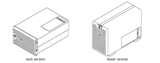
Figure 5-1 shows the rack and tower versions of your system. The illustrations in this document are based on the tower version with the system laying on its side.

Figure 5-1. System Orientation


Removing and Replacing the Front Bezel

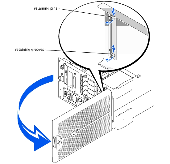
The front bezel has status indicators. Swinging the front bezel open provides access to the power switch, diskette drive, CD drive, hard drive(s), and power supplies. You must open or remove the front bezel and remove the system cover to gain access to internal components.

Removing the Front Bezel

  1. Using the system key, unlock the front bezel.

  2. Pull the bezel away from the system so that it is perpendicular to the system (see Figure 5-2).

Figure 5-2. Removing the Front Bezel

  1. Squeeze the retaining pins (see Figure 5-2).

  2. Rotate the pins upward into the retaining grooves to remove the bezel.

Replacing the Front Bezel

NOTE: The retaining pins are spring loaded. After rotating the pins downward and releasing the pins, they will automatically be inserted into the retaining hinge. You may need to move the bezel slightly to properly align the pins with the retaining hinge.
  1. Align the two bezel retaining pins with the retaining hinge on the front of the system.

  2. Rotate the pins downward, and release the pins to attach the bezel to the system.

  3. Swing the bezel closed until it snaps into place.

  4. Using the system key, lock the bezel.


Removing and Replacing the System Cover

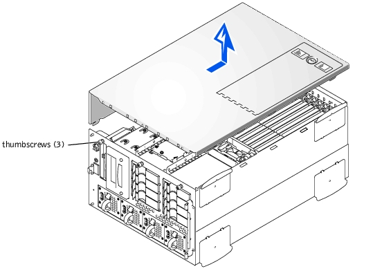
The system is enclosed by a front bezel and a cover. To upgrade or troubleshoot the system, remove the system cover to gain access to internal components.

Removing the System Cover

  1. Open the front bezel (see "Removing the Front Bezel").

  2. Observe the precautions in "Safety First—For You and Your System."

  3. Loosen the three thumbscrews on the front of the system (see Figure 5-3).

Figure 5-3. Removing the System Cover

  1. Slide the system cover backward and grasp the cover at both ends.

  2. Carefully lift the cover away from the system.

Replacing the System Cover

  1. Check that no tools or parts are left inside the system and that any cables are routed so that they will not be damaged by the cover.

  2. Fit the cover over the sides of the chassis, and slide the cover forward.

  3. Secure the cover with the three thumbscrews.

  4. Close the front bezel.


Checking the Equipment

This section provides troubleshooting procedures for equipment that connects directly to the I/O (back) panel of the system, such as the monitor, keyboard, or mouse. Before you perform any of the procedures, see "External Connections."

Troubleshooting the Video Subsystem

Problem
Action
  1. Check the system and power connections to the monitor.

  2. Run the video tests in system diagnostics.

If the tests run successfully, the problem is not related to video hardware. Go to "Finding Software Solutions."

If the tests did not run successfully, see "Getting Help" for instructions on obtaining technical assistance.

Troubleshooting the Keyboard

Problem
Action
  1. Look at the keyboard and the keyboard cable for any signs of damage.

  2. Press and release each key on the keyboard.

If the keyboard and its cable appear to be free of physical damage and the keys work, go to step 4.

If the keyboard or its cable are damaged, continue to step 3.

  1. Swap the faulty keyboard with a working keyboard.

If the problem is resolved, the keyboard must be replaced (see "Getting Help" for instructions on obtaining technical assistance).

  1. Run the keyboard test in system diagnostics.

If you can use the keyboard to select the keyboard test, go to step 6.

If you cannot use the keyboard to select the keyboard test, continue to step 5.

  1. Swap the faulty keyboard with a working keyboard.

  2. Did the keyboard test run successfully?

If the problem is resolved, the faulty keyboard must be replaced.

If the problem is not resolved, the keyboard controller on the system board is faulty (see "Getting Help" for instructions on obtaining technical assistance).

Troubleshooting the Basic I/O Functions

Problem
Action
  1. Enter the System Setup program (see "Using the System Setup Program" in the User's Guide for instructions) and check the Serial Port 1, Serial Port 2, and Parallel Port settings.

If the communications ports are set to Off, go to step 3.

If the communications ports are not set to Off, continue to step 2.

  1. Change the Serial Port 1, Serial Port 2, and Parallel Port settings to Auto; then reboot the system.

  2. Check the settings in the System Setup program (see "Using the System Setup Program" in the User's Guide for instructions).

If the settings are correct, go to step 5.

  1. Change the necessary settings in the System Setup program. If the port problem is confined to a particular application program, see the application program's documentation for specific port configuration requirements.

  2. Reboot the system from the diagnostics diskette, and run the serial port and/or parallel port test(s) in the system diagnostics.

If the test(s) did not run successfully, see "Getting Help" for instructions on obtaining technical assistance.

If the test(s) run successfully but the problem persists, see "Troubleshooting a Parallel Printer" or "Troubleshooting a Serial I/O Device," depending on the malfunctioning device.

Troubleshooting a Serial I/O Device

Problem
Action
  1. Open the front bezel (see "Removing the Front Bezel").

  2. Turn off the system and any peripheral devices connected to the serial ports.

If there is only one serial device connected to the system, go to step 5.

  1. Disconnect all devices from the serial ports, and connect the malfunctioning device to the other port.

  2. Turn on the system.

If the problem is resolved, the serial port may be defective (see "Getting Help" for instructions on obtaining technical assistance).

  1. Swap the interface cable with a known working cable.

If the problem is resolved, the interface cable must be replaced (see "Getting Help" for instructions on obtaining technical assistance).

  1. Turn off power to the system and the serial device, and swap the device with a comparable device.

  2. Turn on the system and the serial device.

If the problem is resolved, the serial device must be replaced.

If the problem is not resolved, see "Getting Help" for instructions on obtaining technical assistance.

Troubleshooting a Parallel Printer

Problem
Action
  1. Run the printer's self-test.See the documentation for your printer for instructions on performing the self-test.

If the printer's self-test fails, see "Getting Help" for instructions on obtaining technical assistance.

If the self-test does not resolve the problem, continue to step 2.

  1. Open the system's front bezel (see "Removing the Front Bezel").

  2. Turn off the printer and the system.

  3. Swap the parallel printer interface cable with a known working cable.

  4. Turn on the printer and the system.

  5. Attempt a print operation.

If the print operation is successful, the interface cable must be replaced (see "Getting Help" for instructions on obtaining technical assistance).

If the print operation is not successful, replace the system board (see "Getting Help" for instructions on obtaining technical assistance).

Troubleshooting a USB Device

Problem
Action
  1. Enter the System Setup program and check that the USB ports are enabled (see "Using the System Setup Program" in the User's Guide for instructions).

  2. Open the front bezel (see "Removing the Front Bezel").

  3. Turn off the system and any USB devices.

If there is only one USB device connected to the system, go to step 6.

  1. Disconnect all USB devices, and connect the malfunctioning device to the other port.

  2. Turn on the system and the reconnected device.

If the problem is resolved, the USB port may be defective (see "Getting Help" for instructions on obtaining technical assistance).

  1. If possible, swap the interface cable with a known working cable.

If the problem is resolved, the interface cable must be replaced (see "Getting Help" for instructions on obtaining technical assistance).

  1. Turn off the system and the USB device, and swap the device with a comparable device.

  2. Turn on the system and the USB device.

If the problem is resolved, the USB device must be replaced.

If the problem is not resolved, see "Getting Help" for instructions on obtaining technical assistance.

Troubleshooting the Integrated NICs

Problem
Action
  1. Check the two indicators on the left and right corners of the NIC connectors on the system's back panel (see Figure 5-4).

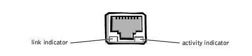
The green indicator shows that the adapter is connected to a valid link partner. The amber activity indicator is on if network data is being sent or received.

Figure 5-4. NIC Indicators

  1. If the activity indicator does not light, the network driver files might be damaged or deleted.

Check the drivers and remove and reinstall the drivers if applicable.

You must reboot your system for the reinstalled drivers to become active.

  1. Make sure the appropriate drivers are installed and the protocols are bound.

  2. Enter the System Setup program and confirm that the NICs are enabled (see "Using the System Setup Program" in the User's Guide for instructions).


Inside the System

In Figure 5-5, the system cover and front bezel are removed to provide an interior view of the system.

Figure 5-5. Inside the System

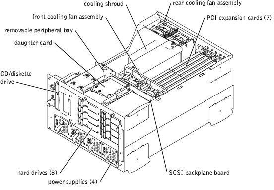
The system board can accommodate up to seven PCI expansion cards (six PCI or PCI-X cards at 64-bit/33–100 MHz and one PCI card at 32-bit/33 MHz). The system memory is contained on two separate riser cards that must be populated with at least two memory modules each for the system to operate. The peripheral bay provides space for a 3.5-inch diskette drive, a CD drive, and two other devices (two hard drives or one tape drive).

The hard-drive bays provide space for up to eight 1-inch SCSI hard drives. These hard drives are connected to a SCSI host adapter on the system board or on an expansion card, via the SCSI backplane board.

The power distribution board (PDB) provides AC switching, hot-plug logic, and power distribution for the system. The system has two AC power inputs available to support AC power redundancy. The system can operate from either input and automatically switches from a failing AC source. Three hot-pluggable power supplies that are front-loadable and slide into connectors mounted on the PDB provide power to the system board, SCSI backplane board, and internal peripherals. There is an option for a fourth hot-pluggable power supply to provide redundant DC power.

For non-SCSI drives such as the diskette drive and CD drive, an interface cable connects the interposer board, attached to the diskette drive and CD drive, to the system board. For SCSI devices, interface cables connect externally accessible SCSI devices and the SCSI backplane board to a SCSI host adapter either on the system board or on an expansion card. For more information, see "Installing Drives."

During an installation or troubleshooting procedure, you may be required to change a jumper. For information on the system board jumpers, see "Jumpers and Connectors."


Responding to a System Management Alert Message

The optional system management applications monitor critical system voltages and temperatures, the system cooling fans, and the status of the SCSI hard drives in the system. Alert messages appear in the alert log window. For information about the alert log window and options, see your system management software documentation.


Troubleshooting a Wet System

Problem
Action
  1. Turn off the system, including any attached peripherals, and disconnect the system from the electrical outlet.

  2. Remove the system cover (see "Removing the System Cover").

  3. Remove all expansion cards installed in the system (see "Removing an Expansion Card" in "Installing System Board Options").

  4. Let the system dry thoroughly for at least 24 hours.

  5. Replace the system cover, reconnect the system to the electrical outlet, and turn on the system.

If the system does not start up properly, see "Getting Help" for instructions on obtaining technical assistance.

  1. If the system starts up normally, shut down the system and reinstall all expansion cards you removed in step 3 (see "Installing an Expansion Card" in "Installing System Board Options").

  2. Run the system board tests in system diagnostics to confirm that the system is working properly.

If the tests did not complete successfully, see "Getting Help" for instructions on obtaining technical assistance.


Troubleshooting a Damaged System

Problem
Action
  1. Check the following connections:

  2. Make sure that all cables are properly connected and that all components are properly seated in their connectors and sockets.

  3. Run the system board tests in system diagnostics.

If the tests did not complete successfully, see "Getting Help" for instructions on obtaining technical assistance.


Troubleshooting the System Battery

Problem

The system battery maintains system configuration, date, and time information in a special section of memory when you turn off the system. The operating life of the battery ranges from 2 to 5 years, depending on how you use the system (for example, if you keep the system on most of the time, the battery gets little use and thus lasts longer). You may need to replace the battery if an incorrect time or date is displayed during the boot routine.

You can operate the system without a battery; however, the system configuration information maintained by the battery in NVRAM is erased each time you remove power from the system. Therefore, you must reenter the system configuration information and reset the options each time the system boots until you replace the battery.

Action
  1. Reenter the time and date through the System Setup program.

  2. Turn off and disconnect the system from the electrical outlet for a few hours.

  3. Reconnect the system to the electrical outlet and turn the system on again.

  4. Enter the System Setup program.

If the date and time are not correct in the System Setup program, replace the battery (see "System Battery").

If the problem is not resolved by replacing the battery, see "Getting Help" for instructions on obtaining technical assistance.

NOTE: Some software may cause the system time to speed up or slow down. If the system seems to operate normally except for the time kept in the System Setup program, the problem may be caused by software rather than by a defective battery.
NOTE: If the system is turned off for long periods of time (for weeks or months), the NVRAM may lose its system configuration information. This situation is not caused by a defective battery.

Troubleshooting Redundant Power Supplies

Problem
Action
  1. Open the front bezel (see "Removing the Front Bezel").

NOTICE: The power supplies are hot-pluggable. The system requires three power supplies to be installed for the system to operate normally. The system is in the redundant mode when all four power supplies are installed. Remove and replace only one power supply at a time.
  1. While grasping the power supply handle, push down on the release lever and pull the power supply straight out to clear the chassis.

  2. Slide the new power supply into the chassis until it snaps into place.


Troubleshooting a Cooling Fan

Problem
Action
  1. Remove the system cover (see "Removing the System Cover").

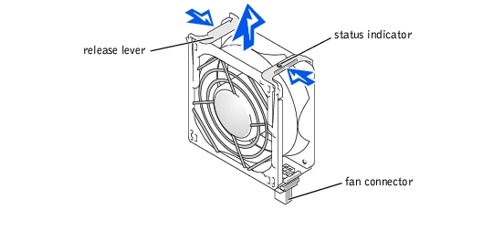
NOTE: There are two fan assemblies. The front fan assembly is located near the SCSI backplane board and contains two fans. The back panel fan assembly is attached to the back panel, memory riser card guides, and the cooling shroud.
NOTE: Each individual fan has a status indicator. If the fan is operating normally, the indicator is green. If the fan is malfunctioning, the indicator is amber.
NOTICE: The cooling fans are hot-pluggable. To maintain proper cooling while the system is on, replace only one fan at a time.
  1. Locate the faulty fan and, while squeezing the release levers, lift the fan straight up to clear the fan assembly (see Figure 5-6).

Figure 5-6. Removing a Cooling Fan

  1. Reseat the fan in its compartment and ensure that the fan connector is firmly seated.

  2. If the problem is not resolved, install a replacement cooling fan.

  3. If the replacement fan does not operate, one of the fan bay connectors is faulty (see "Getting Help" for information on obtaining technical assistance).

NOTE: After installing a new fan, allow up to 30 seconds for the system to recognize the fan and determine whether it is working properly.

Troubleshooting Expansion Cards

Problem
Action
NOTICE: If either the operating system or expansion card does not provide hot-plug support, you must power down the system before removing the expansion card. For more information, see the documentation for your operating system and the expansion card.
  1. Unlock and open the expansion-card access cover.

  2. Press the switch next to each expansion card and wait until the LED turns off.

NOTE: Slot 1 is not a hot-pluggable connector.
  1. Verify that each expansion card is firmly seated in its connector.

  2. Verify that any appropriate cables are firmly connected to their corresponding connectors on the expansion cards.

  3. Press the switch next to each expansion card and wait until the green LED turns on.

  4. Close the expansion-card access cover.

  5. Run the Quick Tests in the system diagnostics.

If the problem still exists, go to step 8.

  1. Open the expansion-card access cover.

  2. Press the switch next to each expansion card and wait until the LED turns off.

  3. Remove all expansion cards installed in the system.

  4. Run the Quick Tests in the system diagnostics.

If the tests do not complete successfully, see "Getting Help" for information on obtaining technical assistance.

  1. Reinstall one of the expansion cards you removed in step 10, press the switch next to the expansion card, and wait until the green LED turns on.

  2. Repeat steps 11 and 12 for each of the remaining expansion cards.

If you have reinstalled all of the expansion cards and the Quick Tests are still failing, see "Getting Help" for information on obtaining technical assistance.


Troubleshooting System Memory

Problem
Action
  1. Turn on the system, including any attached peripherals.

If there are no error messages, go to step 20.

  1. Enter the System Setup program to check the system memory setting (see "Using the System Setup Program" in the User's Guide for instructions).

  2. If the amount of memory matches the system memory setting, go to step 20.

  3. Turn off the system, including any attached peripherals, and disconnect the system from its electrical outlet.

  4. Remove the system cover (see "Removing the System Cover").

  5. Remove the cooling shroud (see "Cooling Shroud" in "Installing System Board Options").

NOTICE: See "Protecting Against Electrostatic Discharge" in the safety instructions in your System Information document.
  1. Remove the two memory riser cards (see "Removing Memory Modules").

  2. Reseat the memory modules in their sockets.

  3. Reinstall the two memory riser cards (see "Installing Memory Modules").

  4. Reinstall the cooling shroud (see "Installing the Cooling Shroud" in "Installing System Board Options").

  5. Replace the system cover, reconnect the system to power, and turn on the system.

  6. Enter the System Setup program and check the system memory again.

If the amount of memory installed does not match the system memory setting, perform the following steps:

    1. Turn off the system.

    1. Remove the system cover.

    2. Remove the cooling shroud.

    3. Go to step 14.

  1. Reboot the system and observe the monitor screen and the Num Lock, Caps Lock, and Scroll Lock indicators on the keyboard.

If the monitor screen remains blank and the Num Lock, Caps Lock, and Scroll Lock indicators on the keyboard remain on, perform the following steps:

    1. Turn off the system.

    1. Remove the system cover.

    2. Remove the cooling shroud.

    3. Remove the memory riser cards.

    4. Go to step 14.

If the monitor screen does not remain blank and the Num Lock, Caps Lock, and Scroll Lock indicators on the keyboard remain on, continue to step 20.

NOTE: There are multiple configurations for the memory modules; see "Memory Module Installation Guidelines" in "Installing System Board Options." The following steps are an example of one configuration.
  1. Swap the memory module pair in bank 1 (A and B) of both memory riser cards with another pair of the same capacity.

  2. Reinstall the memory riser cards (see "Installing Memory Modules").

  3. Install the cooling shroud (see "Installing the Cooling Shroud" in "Installing System Board Options").

  4. Replace the system cover, reconnect the system to power, and turn on the system.

  5. Reboot the system, and observe the monitor screen and the indicators on the keyboard.

  6. If the problem still exists, perform the following tests:

    1. Turn off the system.

    1. Remove the system cover.

    2. Remove the cooling shroud.

    3. Remove the memory riser cards.

    4. Repeat steps 14 through 18 for each memory module pair installed on each riser card.

If the problem is not resolved, see "Getting Help" for instructions on obtaining technical assistance.

  1. Run the system memory test in system diagnostics.

If the test does not complete successfully, see "Getting Help" for instructions on obtaining technical assistance.


Troubleshooting the System Board

Problem
Action
  1. Turn off the system, including any attached peripherals, and disconnect the system from its electrical outlet.

  2. Open the expansion-card access cover.

  3. Remove all expansion cards except the SCSI host adapter card for the boot drive, if applicable.

  4. Close the expansion-card access cover.

  5. Run the Quick Tests in the system diagnostics.

If the tests does not run successfully, see "Getting Help," for instructions on obtaining technical assistance.

  1. Turn off the system, including any attached peripherals, and disconnect the system from its electrical outlet.

  2. Reinstall one of the expansion cards that you removed in step 3.

  3. Connect the system to its electrical outlet and turn on the system, including any attached peripherals.

  4. Close the expansion-card access cover.

  5. Run the Quick Tests again.

If the tests does not complete successfully, see "Getting Help" for instructions on obtaining technical assistance.

  1. Repeat steps 6 through 10 for the remaining expansion cards that you removed in step 3.

If you have reinstalled all of the expansion cards and the problem still persists, see "Getting Help" for instructions on obtaining technical assistance.


Troubleshooting the Diskette Drive

Problem
Action
  1. Enter the system setup program and verify that the system is configured correctly (see "Using the System Setup Program" in the User's Guide).

  2. Run the diskette drive tests from the diagnostics diskette to see whether the diskette drive now works correctly.

  3. Turn off the system, including any attached peripherals, and disconnect the system from its electrical outlet.

  4. Remove the system cover (see "Removing the System Cover").

  5. Verify that the diskette/CD drive interface cable is securely connected between the interposer board on the diskette/CD drive assembly and the system board.

  6. Reinstall the system cover (see "Replacing the System Cover").

  7. Connect the system to its electrical outlet and turn on the system, including any attached peripherals.

  8. Run the diskette drive tests in the system diagnostics to determine whether the diskette drive works correctly.

  9. If the drive still does not work, remove all expansion cards (see "Removing an Expansion Card" in "Installing System Board Options").

  10. Run the diskette drive tests from the system diagnostics diskette to determine whether the diskette drive now works correctly.

If the test ran successfully, an expansion card may be conflicting with the diskette drive logic, or you may have a faulty expansion card. Continue to step 11.

If the test failed, see "Getting Help" for instructions on obtaining technical assistance.

  1. Reinstall one of the expansion cards you removed in step 9 (see "Installing an Expansion Card" in "Installing System Board Options").

  2. Retest and run the diskette drives test in system diagnostics to determine whether the diskette drive subsystem now works correctly.

  3. Repeat steps 11 and 12 until all expansion cards have been reinstalled or until one of the expansion cards prevents the system from booting from the diagnostics diskette.

If the problem is not resolved, see "Getting Help" for instructions on obtaining technical assistance.


Troubleshooting a CD Drive

Problem
Action
  1. Turn off the system, including any attached peripherals, and disconnect the system from its electrical outlet.

  2. Remove the system cover (see "Removing the System Cover").

  3. Verify that the diskette/CD drive interface cable is securely connected between the interposer board on the diskette/CD drive assembly and the system board.

  4. Connect the system to its electrical outlet and turn on the system, including any attached peripherals.

  5. Enter the System Setup program to check that the IDE device is enabled (see "Using the System Setup Program" in the User's Guide).

  6. Run the IDE devices tests in the system diagnostics to determine whether the CD drive now works correctly.

If the problem is not resolved, see "Getting Help" for instructions on obtaining technical assistance.


Troubleshooting an External SCSI Tape Drive

Problem
Action
  1. Remove the tape that was in use when the problem occurred and replace it with a tape that you know is not defective.

  2. Verify that any required SCSI device drivers are installed on the hard drive and are configured correctly.

For instructions on installing and configuring device drivers for the system's integrated SCSI host adapter, see "Using the Dell OpenManage Server Assistant CD" in the User's Guide.

For a SCSI host adapter card, see the documentation that accompanied the card.

  1. Reinstall the tape-backup software as instructed in the tape-backup software documentation.

  2. Check the external cable connections to the drive.

    1. Turn off the system, including any attached peripherals, and disconnect the system from its electrical outlet.

    1. Check the SCSI cable connection to the host adapter card and the SCSI tape drive and the DC power cable connection to the tape drive.

    2. Verify that the tape drive is configured for a unique SCSI ID number and that the tape drive is terminated or not terminated as appropriate.

See the documentation for the tape drive for instructions on selecting the SCSI ID and enabling or disabling termination.

    1. Reconfigure the tape drive's SCSI ID and termination settings as appropriate and reinstall the tape drive.

    2. Replace the SCSI cable that connects the tape drive to the SCSI host adapter.

    3. Reconnect the system to the electrical outlet and turn on the system.

If the problem is not resolved, see "Getting Help" for instructions on obtaining technical assistance.


Troubleshooting Hard Drives

Problem
Action
NOTICE: This troubleshooting procedure can destroy data stored on the hard drive. Before you proceed, back up all the files on the hard drive.
  1. If the integrated SCSI host adapter is being used to control the SCSI backplane board, reboot the system and press <Ctrl><a> to enter the SCSI configuration utility program.

NOTE: If your system has an optional RAID controller installed, reboot the system and press <Ctrl><h>, <Ctrl><a>, or <Ctrl><m>, depending on the utility. See the documentation supplied with the controller for information on the configuration utility.
  1. Check that the primary SCSI channel is enabled, and reboot the system.

  2. Verify that the device drivers are installed and configured correctly (see the operating system's documentation).

  3. Remove the hard drive and install it in the another drive bay.

  4. If the problem is resolved, reinstall the hard drive in the original bay.

If the hard drive functions properly in the original bay, the drive carrier could have intermittent problems. Replace the drive carrier (see "Installing SCSI Hard Drives").

If the drive carrier still does not function properly in the original bay, the SCSI backplane board has a defective connector (see "Getting Help" for instructions on obtaining technical assistance).

  1. Check the SCSI cable connections inside the system:

    1. Turn off the system, including any attached peripherals, and disconnect the system from its electrical outlet.

    1. Remove the system cover (see "Removing the System Cover").

    2. Check the SCSI cable connection to the SCSI host adapter.

The SCSI cable may be connected to the internal SCSI host adapter on the system board or a SCSI host adapter card installed in an expansion slot.

NOTE: To operate the SCSI backplane in a 1 x 8 configuration, make sure that a SCSI cable is connected only to the Channel A connector of the SCSI backplane and that a daughter card is not installed. To operate the SCSI backplane in a 2 x 4 configuration, make sure that both SCSI cables are connected and that a daughter card is installed.
  1. Partition and logically format the hard drive. If possible, restore the files to the drive.

To partition and logically format the drive, see the operating system documentation.

If the problem is not resolved, see "Getting Help" for instructions on obtaining technical assistance.


Troubleshooting an Integrated RAID Controller

Problem
Action
  1. Enter the System Setup program and check the setting for the integrated RAID controller (see "Using the System Setup Program" in the User's Guide).

If the controller is enabled, go to step 4.

  1. Change the RAID controller setting to Enabled, and then reboot the system.

  2. See the documentation provided with the RAID controller software and check the software settings.

CAUTION: Before you perform this procedure, you must turn off the system and disconnect it from its power source. For more information, see "Safety First—For You and Your System."
  1. Turn off the system, including any attached peripherals, and disconnect the system from its electrical outlet.

NOTICE: See "Protecting Against Electrostatic Discharge" in the safety instructions in your System Information document.
  1. Remove the system cover (see "Removing the System Cover").

  2. Reseat the RAID memory module in its socket.

See "Installing Memory Modules" in "Installing System Board Options" for general instructions on removing the RAID memory modules.

  1. Reseat the RAID hardware key in its socket (see "Installing the RAID Hardware Key").

See Figure 6-1 for the location of the RAID hardware key.

  1. Replace the RAID backup battery (see "Installing the RAID Battery").

  2. Replace the system cover, reconnect the system to the electrical outlet, and reboot the system.

If the problem is not resolved, see "Getting Help" for instructions on obtaining technical assistance.


Troubleshooting a RAID Controller Card

Your system may contain an optional RAID controller card. If you encounter problems with the controller, see the RAID controller card's documentation for detailed information on troubleshooting.


Back to Contents Page