Back to Contents Page
Dell™ PowerEdge™ 4600 Systems
Installation and
Troubleshooting Guide
 Removing the Peripheral Bay
Installing the Peripheral Bay
Installing Devices in the Peripheral Bay
Connecting an External SCSI Tape Drive
Installing SCSI Hard Drives
Installing a Host Adapter Expansion Card
Installing a SCSI Backplane Daughter Card
Configuring the Boot Device
Your system features an internal drive bay that contains up to eight SCSI hard drives. Your system also features a removable peripheral bay that can be used for an additional two SCSI hard drives or an internal tape drive. Attached to the removable peripheral bay is a user-accessible, half-height CD drive and a 3.5-inch diskette drive, which are controlled by the IDE/diskette drive controller on the system board. This section contains instructions for replacing these devices as well as upgrading the system by installing an optional SCSI backplane daughter card for split backplane operation or a host adapter card.
- Turn off the system, including any attached peripherals, and disconnect the system
from its electrical outlet.
- Remove the system cover (see "Removing the System Cover" in "Troubleshooting Your
System").
- Remove the front fan assembly (see "Removing the Front Fan Assembly" in "Installing
System Board Options").
- Disconnect the interface cable from the interposer board attached to the CD/diskette
drive.
- Loosen the thumbscrew that secures the peripheral bay to the chassis (see Figure
7-1).
 |
NOTE: To slide the peripheral bay backward, you may need to disconnect the power cable
on the SCSI backplane board.
|
Figure 7-1. Removing the Peripheral Bay
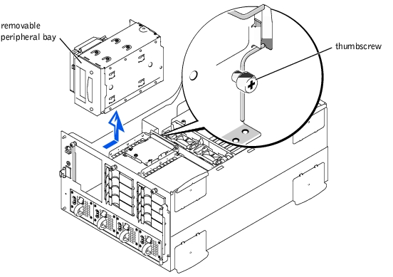
- While grasping the peripheral bay handle, slide the peripheral bay backward and lift it
straight up to clear the chassis.
- While grasping the peripheral bay handle, lower the peripheral bay into the chassis.
- Align the tabs on side of the peripheral bay with the locking slots in the chassis and
slide the peripheral bay forward.
- Tighten the thumbscrew that secures the peripheral bay to the chassis (see Figure
7-1).
- Connect the interface cable from the system board to the CD/diskette drive interposer
board.
- Replace the front fan assembly (see "Replacing the Front Fan Assembly" in "Installing
System Board Options").
- Replace the system cover (see "Replacing the System Cover" in "Troubleshooting Your
System").
The peripheral bay can be used for an additional two SCSI hard drives or an internal tape drive.
If you install a SCSI device, you must connect it to the secondary SCSI interface connector (SCSI_B) on the system board (see Figure 6-1) or to a SCSI host adapter expansion card.
These interface connectors are keyed for correct insertion. Keying ensures that the pin-1 wire in the cable connects to pin 1 in the connectors on both ends.
When you disconnect an interface cable, take care to grasp the cable connector, rather than the cable itself, to avoid stress on the cable.
Although SCSI devices are installed in essentially the same way as other devices, their configuration requirements are different. To configure a SCSI device installed in the peripheral bay, follow the guidelines in the following subsections.
Each device attached to a SCSI host adapter must have a unique SCSI ID number from 0 to 7.
A SCSI tape drive is configured as SCSI ID 6 (the default ID number for a tape drive).
|
NOTE: There is no requirement that SCSI ID numbers be assigned sequentially or that devices
be attached to the cable in order by ID number.
|
SCSI logic requires that the two devices at opposite ends of the SCSI chain be terminated and that all devices in between be unterminated. The SCSI cable included in the upgrade kit has an active terminator installed at the end of the cable. Therefore, when configuring the devices in the peripheral bay, you should disable the device's termination.
SCSI hard drives can be installed in your system using either the integrated AIC-7899 SCSI controller or an added SCSI controller card.

|
CAUTION: Before you perform this procedure, you must turn off the system and
disconnect it from its power source. For more information, see "Safety First—For
You and Your System" in "Troubleshooting Your System."
|
 |
NOTICE: See "Protecting Against Electrostatic Discharge" in the safety instructions in your
System Information document.
|
- Turn off the system, including any attached peripherals, and disconnect the system
from the electrical outlet.
- Prepare the drive for installation.
Ground yourself by touching an unpainted metal surface on the back of the system, unpack the drive, and compare the jumper and switch settings with those in the drive's documentation. See "SCSI Configuration Information" for information on setting the drive's SCSI ID number and enabling termination (if required). Change any settings necessary for your system's configuration.
- Remove the system cover (see "Removing the System Cover" in "Troubleshooting Your
System").
- Disconnect the cable connected to the interposer board on top of the peripheral bay.
This cable is the system board interface cable that connects the interposer board of the CD/diskette drive to the system board.
- Remove the inserts from the front of the peripheral bay.
From the inside of the chassis, push outward on the center of the insert to remove it from the chassis.
- Remove the peripheral bay (see "Removing the Peripheral Bay").
- Slide the 1 x 2 hard-drive bay into the peripheral bay until the holes in the peripheral
bay and the hard-drive bay line up.
- Using four screws, secure the hard-drive bay to the peripheral bay.
There are two screws on top and two screws on the bottom of the peripheral bay that secure the drive in the bay.
- Install the peripheral bay (see "Installing the Peripheral Bay").
- Reconnect the cable to the interposer board on top of the peripheral bay.
- Disconnect the I2C cable connector at the 20-pin SCSI BACKPLANE connector on
the system board.
Do not disconnect the end that is connected to the SCSI backplane.
|
NOTE: The I2C cable must be routed over the top of the cooling shroud.
|
- Route the I2C extension cable through the clips on the top of the cooling shroud (see
Figure 1-3).
The I2C extension cable has three connectors: a 20-pin connector on one end, a 10-pin connector on the other end, and a 20-pin cable connector in the middle
- Attach the 10-pin connector on the I2C extension cable to the 10-pin connector
(PLANAR_1X2) on the 1 x 2 backplane.
- Attach the 20-pin connector on the end of the I2C extension cable to the 20-pin
connector on the system board (SCSI BACKPLANE).
- Attach the free end of the I2C cable, which was disconnected from the system board in
step 11, to the middle connector on the new I2C extension cable that you installed in
steps 13 and 14.
- Slide the system board tray to the first service position (see "Opening the System
Board Tray" in "Installing System Board Options").
- Attach a four-wire power cable to the power connector (J1) on the 1 x 2 backplane
from the power distribution board (J8).
- Close the system board tray (see "Closing the System Board Tray" in "Installing System
Board Options").
- Route the SCSI cable through the clips on top of the cooling shroud.
- On the end with two connectors:
- Attach the connector on the end of the cable to the vertical connector that is
closest to the 10-pin I2C connector on the 1 x 2 backplane.
- Attach the next-to last connector on the cable to the remaining vertical connector
on the 1 x 2 backplane.
- Attach the end with one connector to the SCSI_B connector on the system board.
You can also connect this end of the cable to a PCI SCSI or PCI RAID controller card.
- Check all cable connections that may have been loosened during this procedure.
Arrange cables so that they will not catch on the system cover or block the airflow of the fans or cooling vents.
- Replace the system cover (see "Replacing the System Cover" in "Troubleshooting Your
System").
- Reconnect the system and peripherals to their power sources, and turn them on.
- Test the device(s).
Tape drives use either the integrated AIC-7890 SCSI controller or an expansion card. Tape drives that require their own separate controller cards are shipped with the controller card and an interface cable.
|
|
CAUTION: Before you perform this procedure, you must turn off the system and
disconnect it from its power source. For more information, see "Safety First—For
You and Your System" in "Troubleshooting Your System."
|
|
NOTICE: See "Protecting Against Electrostatic Discharge" in the safety instructions in your
System Information document.
|
- Turn off the system, including any attached peripherals, and disconnect the system
from the electrical outlet.
- Prepare the controller card and drive for installation.
Ground yourself by touching an unpainted metal surface on the back of the system, unpack the drive and controller card, and compare the jumper and switch settings with those in the drive documentation. Change any settings necessary for your system's configuration.
- Remove the system cover (see "Removing the System Cover" in "Troubleshooting Your
System").
- Disconnect the cable connected to the interposer board on the peripheral bay.
This cable is the system board interface cable that connects the interposer board of the CD/diskette drive to the system board.
- Remove the inserts from the front of the peripheral bay.
- From the inside of the chassis, push outward on the center of the insert to remove it
from the chassis.
- Remove the peripheral bay (see "Removing the Peripheral Bay").
- Slide the tape drive into the peripheral bay until the holes in the peripheral bay and
the tape drive line up.
- Using four screws, secure the drive to the peripheral bay.
- Install the peripheral bay (see "Installing the Peripheral Bay").
- Slide the system board tray to the first service position (see "Opening the System
Board Tray" in "Installing System Board Options").
- Connect the power cable to the power distribution board.
- Install the controller card in an expansion-card slot (see "Installing an Expansion Card"
in "Installing System Board Options").
- Attach the interface cable that came with the drive to the interface connector on the
back of the drive.
- Connect the tape drive to the cable provided with the device, and attach the other end
of the cable to interface connector SCSI_B on the system board.
|
NOTE: Route the cable over the top of the cooling shroud.
|
- Close the system board tray (see "Closing the System Board Tray" in "Installing System
Board Options").
- Check all cable connections that may have been loosened during this procedure, and
arrange cables so that they will not catch on the system cover or block the airflow of
the fans or cooling vents.
- Replace the system cover (see "Replacing the System Cover" in "Troubleshooting Your
System").
- Reconnect the system and peripherals to their power sources, and turn them on.
- Perform a tape backup and verification test with the drive as instructed in the tape-
drive software documentation that came with the drive.
This subsection describes how to configure and install an external SCSI tape drive.
|
NOTICE: See "Protecting Against Electrostatic Discharge" in the safety instructions in your
System Information document.
|
- Turn off the system, including any attached peripherals, and disconnect the system
from the electrical outlet.
- Prepare the tape drive for installation.
Ground yourself by touching an unpainted metal surface on the back of the system, unpack the drive and controller card, and compare the jumper and switch settings with those in the drive documentation. See "SCSI Configuration Information" for information on setting the drive's SCSI ID number and enabling termination (if required). Change any settings necessary for your system's configuration.
- Unpack the tape drive (and controller card, if applicable), and configure the tape drive
for the system according to the documentation that came with the tape drive.
- If the tape drive was supplied with a controller card, perform the following steps to
install the card:
- Open the expansion-card access cover.
- Install the controller card in an expansion slot (see "Installing an Expansion Card"
in "Troubleshooting Your System").
- Close the expansion-card access cover.
- Connect the tape drive's interface/DC power cable to the external SCSI connector on
the back of the system or to the connector on the controller card supplied with the
tape drive.
- Secure the controller card connection by tightening the screws on the connector.
- Reconnect the system and peripherals to electrical outlets, and turn them on.
- Perform a tape backup and verification test with the drive as instructed in the software
documentation that came with the drive.
This subsection describes how to install and configure SCSI hard drives in the system's internal hard-drive bays and how to upgrade the system by installing a host adapter expansion card.
The internal hard-drive bays provide space for up to eight 1-inch hard drives. These drives connect to a SCSI backplane board. A SCSI cable connects the SCSI backplane board to the SCSI host adapter connector on the system board or to an optional SCSI host adapter card.
Before attempting to remove or install a drive while the system is running, see the documentation for the host adapter card to ensure that the card is configured correctly to support hot-pluggable drive removal and insertion.
SCSI hard drives are supplied in special drive carriers that fit in the hard-drive bays.
|
NOTE: It is recommended that you use only drives that have been tested and approved for use
with the SCSI backplane board.
|
Refer to the following guidelines when configuring the SCSI drive:
- Disable termination on the drive. The SCSI backplane board provides termination for
the SCSI bus.
- Set the SCSI ID on all drives to 0. All SCSI ID numbers for the drives are set by the
SCSI backplane board.
- Configure the drive so that the drive motor waits for a Start Unit command from the
SCSI host adapter before spinning.
You may need to use different programs than those provided with the operating system to partition and format SCSI hard drives. See "Installing and Configuring SCSI Drivers" in the User's Guide for information and instructions.
|
NOTICE: Do not turn off or reboot your system while the drive is being formatted. Doing so can
cause a drive failure.
|
When you format a high-capacity SCSI hard drive, allow enough time for the formatting to be completed. Long format times for these drives are normal. A 9-GB hard drive, for example, can take up to 2.5 hours to format.
|
NOTICE: Hot-plug drive installation is not supported for systems without an integrated RAID
controller or a host adapter expansion card.
|
- If the system does not have a RAID controller installed, shut down the system.
- Open the front bezel (see "Removing the Front Bezel" in "Troubleshooting Your
System").
- Open the hard-drive handle (see Figure 7-2).
Figure 7-2. Installing a SCSI Hard-Drive
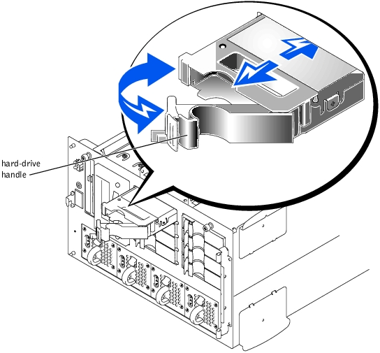
- Insert the hard drive into the drive bay (see Figure 7-2).
- Close the hard-drive handle to lock it in place.
- Close the front bezel (see "Replacing the Front Bezel" in "Troubleshooting Your
System").
- Install any required SCSI device drivers (see "Installing and Configuring SCSI Drivers"
in the User's Guide for information).
- If the hard drive is a new, run the SCSI Controllers test in system diagnostics.
|
NOTICE: Hot-plug drive installation is not supported for systems without an integrated RAID
controller or host adapter expansion card.
|
- If the system does not have a RAID controller installed, shut down the system.
- For systems with host adapter expansion cards, power down the hard-drive bay and
wait until the SCSI hard-drive indicator codes on the drive carrier signal that the drive
may be removed safely.
If the drive has been online, the drive status indicators will flash sequentially as the drive is powered down. When all indicators are off, the drive is ready for removal.
- Open the front bezel (see "Removing the Front Bezel" in "Troubleshooting Your
System").
- Open the hard-drive handle to release the drive.
- Slide the hard drive out until it is free of the drive bay.
- Close the front bezel (see "Replacing the Front Bezel" in "Troubleshooting Your
System").
Follow these general guidelines when installing a host adapter expansion card. For specific instructions, see the documentation supplied with the host adapter expansion card.
|
|
CAUTION: Before you perform this procedure, you must turn off the system and
disconnect it from its power source. For more information, see "Safety First—For
You and Your System" in "Troubleshooting Your System."
|
|
NOTICE: See "Protecting Against Electrostatic Discharge" in the safety instructions in your
System Information document.
|
- Unpack the host adapter expansion card, and prepare it for installation.
For instructions, see the documentation accompanying the card.
- Remove the system cover (see "Removing the System Cover" in "Troubleshooting Your
System").
- Remove the SCSI interface cable that connects the SCSI_ A host-adapter connector
on the system board to the SCSIA connector on the SCSI backplane board (see
Figure 6-1).
- Install the host adapter expansion card.
- Connect the SCSI interface cable supplied with the card to the SCSIA connector on
the SCSI backplane board.
To identify the correct connector, see documentation for the card. Route the SCSI cable under the front fan assembly.
- Connect the external SCSI devices to the card's external connector on the system's
back panel.
If you are attaching multiple external SCSI devices, daisy-chain the devices to each other using the cables shipped with each device.
- Replace the system cover (see "Replacing the System Cover" in "Troubleshooting Your
System").
- Reconnect the system to an electrical outlet and turn it on.
- Connect the external device(s) to electrical outlet(s) and turn them on.
- Install any required SCSI device drivers (see "Installing and Configuring SCSI Drivers"
in the User's Guide).
- Test the SCSI devices.
Test a SCSI hard drive by running the SCSI Controllers test in the system diagnostics.
To operate the SCSI backplane in a 2 x 4 split backplane configuration, you must install a daughter card.
|
|
CAUTION: Before you perform this procedure, you must turn off the system and
disconnect it from its power source. For more information, see "Safety First—For
You and Your System" in "Troubleshooting Your System."
|
- Turn off the system, including any attached peripherals, and disconnect the system
from the electrical outlet.
|
NOTICE: See "Protecting Against Electrostatic Discharge" in the safety instructions in your
System Information document.
|
- Unpack the SCSI backplane board daughter card kit.
- Remove the system cover (see "Removing the System Cover" in "Troubleshooting Your
System").
- The daughter card fits between the sides of a card guide above the drive bay. To install
the daughter card in the card guide, performing the following steps:
- Hold the daughter card by its edges with the component side facing up and the
card connector facing the SCSI backplane board (see Figure 7-3).
Figure 7-3. Installing a SCSI Backplane Daughter Card
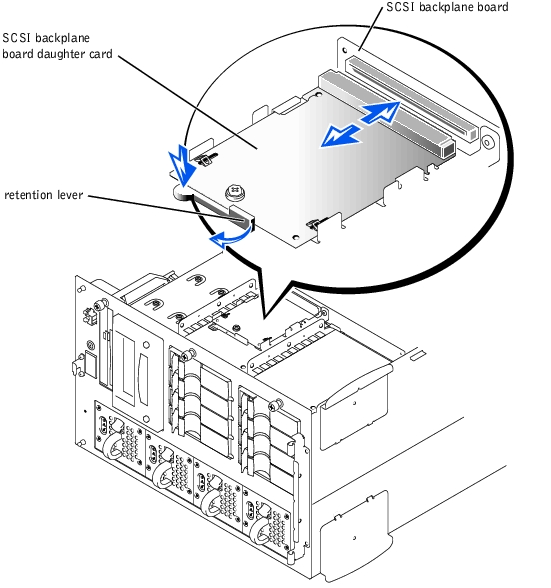
- Ensure that the retention lever is in the open position.
- Position the card in the drive bay so that the notches on the left and right edges of
the card are aligned with the tabs on the card guide above the drive bay.
- Lower the card into the card guide.
- Close the retention lever to slide the daughter card into the SCSI backplane connector
and lock the card into place (see Figure 7-3).
- Reconfigure the SCSI cable connections to the SCSI backplane as necessary to
operate the backplane as a 2 x 4 split backplane.
- Replace the system cover (see "Replacing the System Cover" in "Troubleshooting Your
System").
- Reconnect the system and peripherals to their power sources and turn them on.
If you plan to boot the system from a hard drive, the drive must be attached to the primary (or boot) controller or SCSI host adapter card. The device that the system boots from is determined by the boot order specified in the System Setup program.
The System Setup program provides options that the system uses to scan for installed boot devices. Refer to your system's User's Guide for information about the System Setup program.
Back to Contents Page