Back to Contents Page
Dell™ PowerEdge™ 4600 Systems
Installation and
Troubleshooting Guide
 Fan Assemblies
Individual Fans
Power Supplies
Expansion Cards
Cooling Shroud
Memory Riser Cards
Adding Memory
Microprocessor Upgrades
System Board Tray
Activating the Integrated RAID Controller
System Battery
This section describes how to install the following options:
- Expansion cards
- Memory upgrades
- Microprocessor upgrades
- Activating the integrated RAID controller
This section also includes instructions for replacing the fan assemblies, cooling shroud, power supplies, RAID battery, and system battery, if necessary.
Use Figure 6-1 to locate the system board features. Table 6-1 describes the system board connectors and sockets.
Figure 6-1. System Board Connectors and Sockets
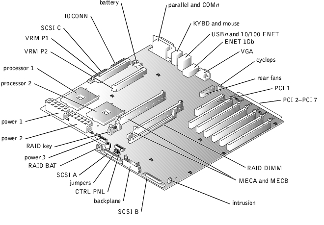
Table 6-1. System Board Connectors and Sockets
|
Connector or Socket
|
Description
|
|---|
10/100 ENET | NIC connector |
BACKPLANE | SCSI backplane board interface cable connector |
BATTERY | System battery connector |
CNTL PNL | System control panel connector |
COMn | Serial port connectors; sometimes referred to as COM1 and COM2 |
CYCLOPS | Power connector for the back-panel status indicator |
ENET_1GB | NIC connector |
INTRUSION | Intrusion switch connector |
IOCONN | Power and data to the diskette/CD interposer board from the system board |
KYBD | Keyboard connector |
MECA, MECB | Memory riser card connectors (2) |
MOUSE | Mouse connector |
PARALLEL | Parallel port connector; sometimes referred to as LPT1 |
PCI_n | Expansion-card connectors. The PCI 1 expansion-card connector operates at 33 MHz. Expansion-card connectors PCI 2 through PCI 7 can operate at 33, 66, or 100 MHz and are hot-pluggable. |
POWERn | Power connectors (3) |
PROCESSOR_n | Microprocessor sockets (2) |
RAID BAT | RAID battery connector |
RAID_DIMM | Memory module connector for integrated RAID controller |
REAR FANS | Power for the back fan assembly |
RAID_KEY | Connector for integrated RAID controller hardware key |
SCSI_n | Ultra160/m SCSI host adapter connectors (SCSI A, B, and C) |
USBn | USB connectors (2) |
VGA | Video connector |
VRM_Pn | Voltage regulator module (VRM) connectors (2) |
NOTE: For the full name of an abbreviation or acronym used in this table, see "Abbreviations and
Acronyms."
|
The system includes two fan assemblies containing a total of six fans. The front fan assembly contains two fans and the back fan assembly contains four fans.

|
CAUTION: Before you perform this procedure, you must turn off the system and
disconnect it from its power source. For more information, see "Safety First—For
You and Your System" in "Troubleshooting Your System."
|
- Remove the system cover (see "Removing the System Cover" in "Troubleshooting Your
System").
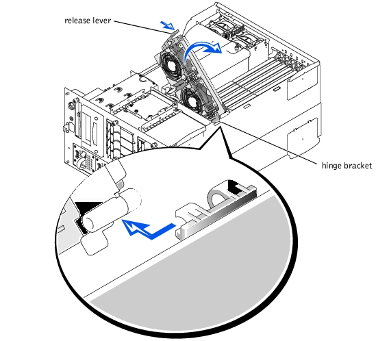
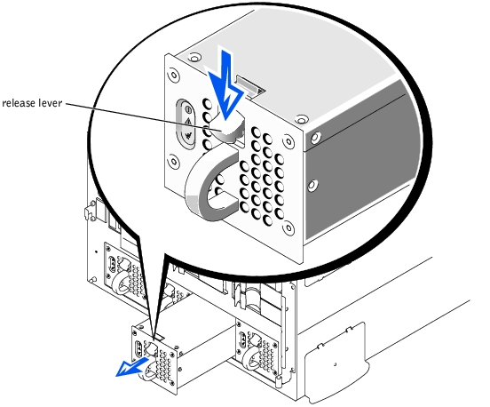
- Release the fan assembly by pressing and holding the release lever (see Figure 6-2).
- Swing the fan assembly up and then slide it forward to remove it from the hinge
bracket.
- Disconnect the fan assembly power cable from the front fan connector on the SCSI
backplane board (see Figure A-3).
- Connect the fan assembly power cable to the front fan connector on the SCSI
backplane board (see Figure A-3).
- Place the fan assembly in the hinge bracket and then slide it backward.
- Swing the fan assembly down until the release lever snaps into place.
- Replace the system cover.
- Close the front bezel.
Figure 6-2. Removing the Front Fan Assembly
- Remove the system cover (see "Removing the System Cover" in "Troubleshooting Your
System").
- Remove the cooling shroud (see "Cooling Shroud").
- Remove the memory riser cards (see "Removing the Memory Riser Cards").
- Disconnect the fan assembly power cable from the fan connector (REAR FANS) on
the system board (see Figure 6-1).
- Press the release latch and lift the fan assembly straight up to clear the chassis (see
Figure 6-3).
Figure 6-3. Removing the Back Fan Assembly
- Align the fan assembly with the fan assembly guide on the back panel, and push down
until the fan assembly is firmly seated and the latch is engaged.
- Connect the fan assembly power cable to the fan connector (REAR FANS) on the
system board (see Figure 6-1).
- Install the memory riser cards (see "Installing the Memory Riser Cards").
- Install the cooling shroud (see "Installing the Cooling Shroud").
- Replace the system cover (see "Replacing the System Cover" in "Troubleshooting Your
System").
The procedures for each individual fan are the same.
- Remove the system cover (see "Removing the System Cover" in "Troubleshooting Your
System").
 |
NOTICE: The cooling fans are hot-pluggable. To maintain proper cooling while the system is
on, replace only one fan at a time.
|
- Locate the faulty fan and while squeezing the fan release levers, lift the fan straight up
to clear the fan assembly (see Figure 6-4).
Figure 6-4. Removing/Replacing a Fan
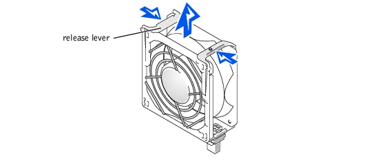
- Lower the fan into the fan assembly until the fan snaps into position.
- Replace the system cover (see "Replacing the System Cover" in "Troubleshooting Your
System").
- Open the front bezel (see "Removing the Front Bezel" in "Troubleshooting Your
System").
|
NOTICE: The power supplies are hot-pluggable. The system requires three power supplies to be
installed for the system to operate normally. The system is in the redundant mode when all four
power supplies are installed. Remove and replace only one power supply at a time.
|
- Remove the power supply by grasping the power supply handle, pressing down on the
release lever, and pulling the power supply straight out to clear the chassis (see Figure
6-5).
Figure 6-5. Removing and Installing the Power Supply
- Install the new power supply by sliding the new power supply into the chassis until it
snaps into place.
- Close the front bezel (see "Replacing the Front Bezel" in "Troubleshooting Your
System").
Seven expansion card slots are available in the system. Expansion-card slots 2 through 7 are hot-pluggable and capable of operating at 33, 66, or 100 MHz. These six expansion-card slots are on three different buses. Slots 2 and 3 are on one bus, slots 4 and 5 are on another bus, and slots 6 and 7 are on a third bus. If you are installing a remote access card, it must be installed in slot 1. Slot 1 is not hot-pluggable and operates at 33 MHz.
You can install expansion cards of different operating speeds on the same bus; however, the bus will operate at the slowest operating speed of the cards on that bus. For example, if one card on the bus has an operating speed of 66 MHz and the other card has an operating speed of 100 MHz, the bus will only operate at 66 MHz.
For optimum performance, you may want expansion cards are on the same bus to have the same operating speed.
|
|
CAUTION: If you are installing an expansion card in expansion-card slot 1, you
must turn off the system and disconnect it from its power source. For more
information, see "Safety First—For You and Your System" in "Troubleshooting
Your System."
|
|
|
CAUTION: If your system's operating system does not support hot-plug PCI or
PCI-X expansion cards or the expansion card itself does not support hot-plug
installation, turn off the system, including any attached peripherals, and
disconnect the system from its electrical outlet.
|
- Unlock and open the expansion-card access cover.
See the documentation that came with the expansion card for information on configuring the card, making internal connections, or otherwise customizing the card for your system.
|
NOTICE: See "Protecting Against Electrostatic Discharge" in the safety instructions in your
System Information document.
|
- Rotate the expansion-card latch, and remove the filler bracket from the
expansion-card slot (see Figure 6-6).
- If your system's operating system does not support hot-plug expansion cards, turn off
the system, including any attached peripherals, and disconnect the system from its
electrical outlet.
If your system's operating system does support hot-plug expansion cards, press the switch next to the expansion-card slot and wait until the LED turns off.
- Install the expansion card (see Figure 6-6):
- Position the expansion card so that the card-edge connector aligns with the
expansion-card connector on the system board.
- Insert the card-edge connector firmly into the expansion-card connector until the
card is fully seated.
Figure 6-6. Installing an Expansion Card
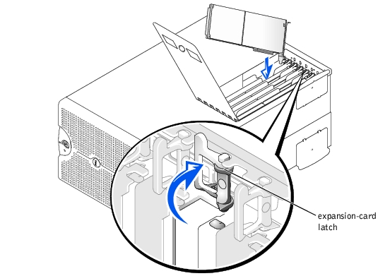
- When the card is seated in the connector and the card-mounting bracket is aligned
with the brackets on either side of it, close the expansion-card latch.
- Connect any cables that should be attached to the card.
See the documentation that came with the card for information about its cable connections.
 |
NOTE: SCSI cables connected from an expansion card to the SCSI backplane board
should be routed under the front fan assembly.
|
|
NOTE: If there is an expansion card in the other expansion card slot on that bus and the
expansion card that you are installing has a different operating speed, you must also power
down the expansion card that is already installed. This will ensure that both expansion cards
on that bus will power up at the slower operating speed.
|
- Press the switch next to the expansion card that you installed and wait until the LED
turns green.
If you turned off your system in step 3 due to your system's operating system not supporting hot-plug expansion cards, close the expansion-card access cover, reconnect the system to its electrical outlet, including any attached peripherals, and turn on the system.
- Close the expansion-card access cover.
|
|
CAUTION: If you are removing an expansion card from expansion-card slot 1,
you must turn off the system and disconnect it from its power source. For more
information, see "Safety First—For You and Your System" in "Troubleshooting
Your System."
|
|
|
CAUTION: If your system's operating system does not support hot-plug PCI or
PCI-X expansion cards or the expansion card itself does not support hot-plug
removal, turn off the system, including any attached peripherals, and disconnect
the system from its electrical outlet.
|
|
NOTICE: See "Protecting Against Electrostatic Discharge" in the safety instructions in your
System Information document.
|
- Unlock and open the expansion-card access cover.
- Press the switch next to the expansion card that you are removing and wait until the
LED turns off.
|
NOTE: Slot 1 is not a hot-pluggable connector.
|
- Disconnect any cables connected to the card.
- To release the expansion card, rotate the latch to the open position (see Figure 6-6).
- Grasp the expansion card by its top corners, and carefully remove it from the
expansion-card connector.
- If you are removing the card permanently, install a metal filler bracket over the empty
card-slot opening.
|
NOTE: Installing a filler bracket over an empty expansion-card slot is necessary to
maintain Federal Communications Commission (FCC) certification of the system. The
brackets also keep dust and dirt out of the system and aid in proper cooling and airflow
inside the system.
|
- If the card is a SCSI controller, remove any SCSI cables attached to connectors SCSI A
and B on the system board (see Figure 6-1). These cables are routed under the front
fan assembly.
- Close the expansion-card access cover.
The cooling shroud is attached to the back fan assembly and the memory riser card guide.
- Turn off the system, including any attached peripherals, and disconnect the system
from the electrical outlet.
- Remove the system cover (see "Removing the System Cover" in "Troubleshooting Your
System").
|
NOTE: There are cables routed over the cooling shroud through retaining clips. You must
remove the cables from the retaining clips before you can remove the cooling shroud.
|
- Remove the cables from the cooling shroud's retaining clips.
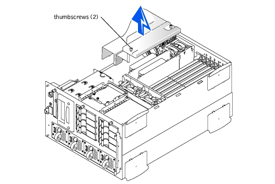
- Loosen the two thumbscrews securing the cooling shroud to the system (see Figure
6-7).
- Lift the cooling shroud up to clear the memory riser cards and the chassis (see Figure
6-7).
Figure 6-7. Removing and Installing the Cooling Shroud
- Lower the cooling shroud into the chassis, ensuring that the cooling shroud is aligned
with the back fan assembly and the memory riser card cage.
- Tighten the two thumbscrews securing the cooling shroud to the system (see Figure
6-7).
- Reroute the cables over the cooling shroud using the retaining clips.
- Replace the system cover.
- Close the front bezel.
The system contains two memory riser cards. Each card contains up to six memory modules.
- Turn off the system, including any attached peripherals, and disconnect the system
from the electrical outlet.
- Remove the system cover (see "Removing the System Cover" in "Troubleshooting Your
System").
- Remove the cooling shroud (see "Removing the Cooling Shroud").
- Grasp the memory riser card by the extractor tabs, located on the top corners of the
card, and lift it straight up to clear the chassis (see Figure 6-8).
Figure 6-8. Removing and Installing Memory Riser Cards
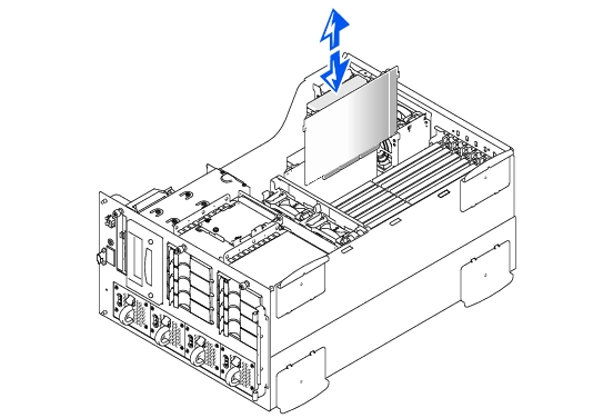
- Position the memory riser card so that the card-edge connector is aligned with the riser
card connector on the system board.
- Insert the card-edge connector firmly into the memory riser card connector until the
card is fully seated.
- Reinstall the cooling shroud (see "Installing the Cooling Shroud").
- Reinstall the system cover (see "Replacing the System Cover" in "Troubleshooting Your
System").
The memory modules are contained on two memory riser cards. Each riser card has six memory module sockets. Between the two memory riser cards, the system can accommodate 512 MB to 12 GB of registered memory modules. The memory module sockets on each riser card are arranged in pairs (A and B) on three banks (1– 3). Memory modules must be installed in at least one bank on each memory riser card for the system to operate. The memory modules should be installed starting with bank 1, then bank 2, and then bank 3 (see Figure 6-9). Each bank on each memory riser card must contain the same memory module size. For example, if bank 1 on one riser card contains 128-MB memory modules, bank 1 on the other riser card must also contain 128-MB memory modules.
To obtain the desired total memory for your system, you may need to install memory modules of different sizes. This is supported as long as the memory modules installed in each bank are the same size and the largest size is installed in bank 1. For example, if you wanted the total memory in your system to be 6 GB, each memory riser card configuration could be as follows:
The system is upgradable to 12 GB by installing combinations of 128-, 256-, 512-MB, and 1-GB registered memory modules. You can purchase memory upgrade kits as needed.
|
NOTE: The memory modules must be PC-1600 compliant.
|
Starting with the socket nearest the top of the memory riser card, the memory module sockets are labeled BANK1_A and BANK1_B through BANK3_A and BANK3_B (see Figure 6-9). When you install memory modules, follow these guidelines:
- You must install memory modules in matched sets of four, two in each memory riser
card.
- Install a pair of memory modules in socket BANK1_A and BANK1_B before installing
a second pair in sockets BANK2_A and BANK2_B.
Figure 6-9. Memory Module Sockets
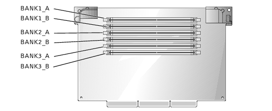
Table 6-3 lists several sample memory configurations based on these guidelines.
Table 6-3. Sample Memory Module Configurations
|
Total Desired
Memory
|
BANK1
|
BANK2
|
BANK3
|
|---|
|
A
|
B
|
A
|
B
|
A
|
B
|
|---|
512 MB | 128 MB | 128 MB | None | None | None | None |
1 GB | 128 MB | 128 MB | 128 MB | 128 MB | None | None |
1 GB | 256 MB | 256 MB | None | None | None | None |
2 GB | 512 MB | 512 MB | None | None | None | None |
4 GB | 512 MB | 512 MB | 512 MB | 512 MB | None | None |
4 GB | 1 GB | 1 GB | None | None | None | None |
6 GB | 1 GB | 1 GB | 512 MB | 512 MB | None | None |
12 GB | 1 GB | 1 GB | 1 GB | 1 GB | 1 GB | 1 GB |
NOTE: This table is a sample configuration of just one memory riser card. For the total desired
memory, you must configure both riser cards identically with the same memory module sizes.
|
|
|
CAUTION: Before you perform this procedure, you must turn off the system and
disconnect it from its power source. For more information, see "Safety First—For
You and Your System" in "Troubleshooting Your System."
|
|
NOTICE: See "Protecting Against Electrostatic Discharge" in the safety instructions in your
System Information document.
|
- Turn off the system, including any attached peripherals, and disconnect the system
from the electrical outlet.
- Remove the system cover (see "Removing the System Cover" in "Troubleshooting Your
System").
- Remove the cooling shroud (see "Cooling Shroud").
- Remove the memory riser cards (see "Removing the Memory Riser Cards").
- Install or replace the memory module pairs on each memory riser card as necessary to
reach the desired memory total (see "Installing Memory Modules" and "Removing
Memory Modules").
See Figure 6-9 for the memory module socket locations on each memory riser card.
- Reinstall the memory riser cards (see "Installing the Memory Riser Cards").
- Reinstall the cooling shroud (see "Installing the Cooling Shroud").
- Reinstall the system cover, reconnect the system to the electrical outlet, and turn on
the system.
After the system completes the POST routine, it runs a memory test.
The system detects that the new memory does not match the system configuration information, which is stored in NVRAM. The monitor displays an error message that ends with the following words:
Press <F1> to continue; <F2> to enter System Setup
- Press <F2> to enter the System Setup program, and check the System Memory
setting in the system data box.
The system should have already changed the value in the System Memory setting to reflect the newly installed memory.
- If the System Memory value is incorrect, one or more of the memory modules may not
be installed properly. Repeat steps 1 through 4 again, checking to make sure that the
memory modules are firmly seated in their sockets.
- Run the system memory test in system diagnostics.
|
|
CAUTION: Before you perform this procedure, you must turn off the system and
disconnect it from its power source. For more information, see "Safety First—For
You and Your System" in "Troubleshooting Your System."
|
|
NOTICE: See "Protecting Against Electrostatic Discharge" in the safety instructions in your
System Information document.
|
- Turn off the system, including any attached peripherals, and disconnect the system
from the electrical outlet.
- Remove the system cover (see "Removing the System Cover" in "Troubleshooting Your
System")
- Remove the cooling shroud (see "Cooling Shroud").
- Remove the memory riser cards (see "Removing the Memory Riser Cards").
- Locate the memory module sockets on each memory riser card in which you will install
a memory module (see Figure 6-9).
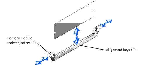
- Press down and outward on the memory module socket ejectors, as shown in Figure
6-10, to allow the memory module to be inserted into the socket.
Figure 6-10. Installing a Memory Module
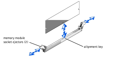
- Align the memory module's edge connector with the alignment key, and insert the
memory module in the socket (see Figure 6-10).
The memory module socket has an alignment key that allows the memory module to be installed in the socket in only one way.
- Press down on the memory module with your thumbs while pulling up on the ejectors
with your index fingers to lock the memory module into the socket (see Figure 6-10).
When the memory module is properly seated in the socket, the memory module socket ejectors should align with the ejectors on the other sockets with memory modules installed.
- Repeat steps 5 through 8 of this procedure to install the remaining memory modules.
- Perform steps 6 through 11 of the procedure in "Performing a Memory Upgrade."
|
|
CAUTION: Before you perform this procedure, you must turn off the system and
disconnect it from its power source. For more information, see "Safety First—For
You and Your System" in "Troubleshooting Your System."
|
|
NOTICE: See "Protecting Against Electrostatic Discharge" in the safety instructions in your
System Information document.
|
- Turn off the system, including any attached peripherals, and disconnect the system
from the electrical outlet.
- Remove the system cover (see "Removing the System Cover" in "Troubleshooting Your
System").
- Remove the cooling shroud (see "Cooling Shroud").
- Remove the memory riser cards (see "Removing the Memory Riser Cards").
- Locate the memory module sockets on each memory riser card in which you will
remove memory modules (see Figure 6-9).
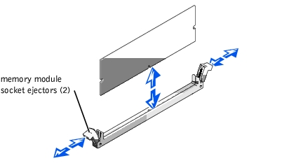
- Press down and outward on the memory module socket ejectors until the memory
module pops out of the socket (see Figure 6-11).
Figure 6-11. Removing a Memory Module
To take advantage of future options in speed and functionality, you can add a second microprocessor or replace either the primary or secondary microprocessor.
|
NOTICE: The second microprocessor must be of the same type as the first. If the two
microprocessors are different speeds, both will operate at the speed of the slower
microprocessor.
|
Each microprocessor and its associated cache memory are contained in a PGA package that is installed in a ZIF socket on the system board. A second ZIF socket accommodates a secondary microprocessor.
In a single microprocessor system, the microprocessor must be installed in the PROCESSOR_1 ZIF socket.
The following items are included in the microprocessor upgrade kit:
- A microprocessor
- A heat sink
- Two securing clips
- A VRM, if adding a second microprocessor
|
NOTICE: See "Protecting Against Electrostatic Discharge" in the safety instructions in your
System Information document.
|
- Turn off the system, including any attached peripherals, and disconnect the system
from the electrical outlet.
- Remove the system cover (see "Removing the System Cover" in "Troubleshooting Your
System").
- Remove the cooling shroud (see "Cooling Shroud").
If you are installing a second microprocessor, go to step 10.
- Press down on the heat-sink securing clips to release the clips from the retaining tabs
on the ZIF socket (see Figure 6-12).
- Remove the securing clips.
|
|
CAUTION: The microprocessor and heat sink can become extremely hot. Be sure
the microprocessor has had sufficient time to cool before handling.
|
|
NOTICE: Never remove the heat sink from a microprocessor unless you intend to remove the
microprocessor. The heat sink is necessary to maintain proper thermal conditions.
|
Figure 6-12. Heat-Sink Securing Clips
- Remove the heat sink.
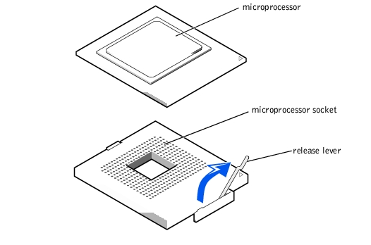
- Pull the socket release lever straight up until the microprocessor is released (see
Figure 6-13).
- Lift the microprocessor out of the socket and leave the release lever up so that the
socket is ready for the new microprocessor.
|
NOTICE: Be careful not to bend any of the pins when removing the microprocessor. Bending
the pins can permanently damage the microprocessor.
|
Figure 6-13. Removing the Microprocessor
- Unpack the new microprocessor.
If any of the pins on the microprocessor appear bent, see "Getting Help" for instructions on obtaining technical assistance.
- If the release lever on the microprocessor socket is not all the way up, move it to that
position now.
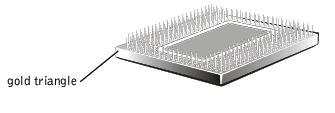
- Align the gold triangle on the microprocessor (see Figure 6-14) with the triangle on
the microprocessor socket.
|
NOTE: Zero insertion force is needed to install the microprocessor. If the microprocessor is
aligned correctly, it should drop into the microprocessor socket.
|
Figure 6-14. Pin-1 Identification
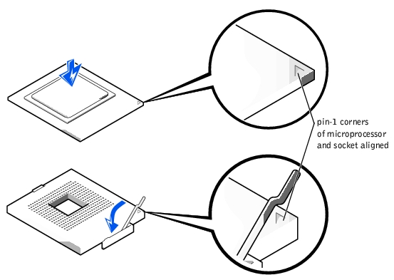
- Install the microprocessor in the socket (see Figure 6-15).
|
NOTICE: Positioning the microprocessor incorrectly can permanently damage the
microprocessor and the system when you turn on the system. When placing the microprocessor
in the socket, be sure that all of the pins on the microprocessor go into the corresponding holes.
Be careful not to bend the pins.
|
- When the microprocessor is fully seated in the socket, rotate the socket release lever
back down until it snaps into place, securing the microprocessor.
Figure 6-15. Installing the Microprocessor
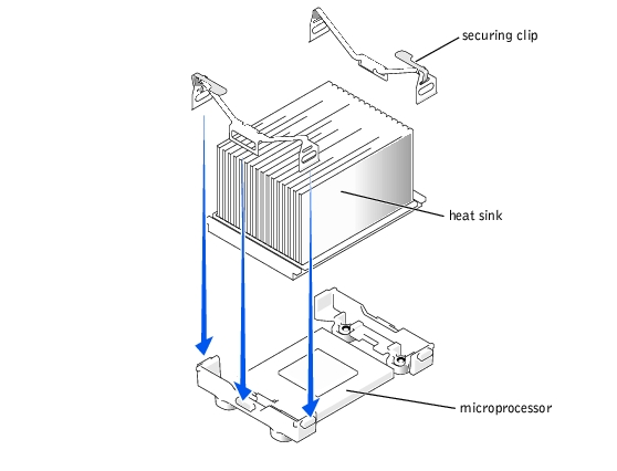
- Place the new heat sink on top of the microprocessor (see Figure 6-16).
- Orient the securing clips as shown in Figure 6-16.
Figure 6-16. Installing the Heat-Sink
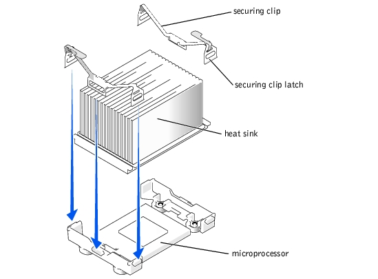
- Hook the end of the clips without the latch to the tab on the edge of the socket.
- Push down and pivot the securing clip latch until the hole on the clip latches onto the
ZIF socket tab.
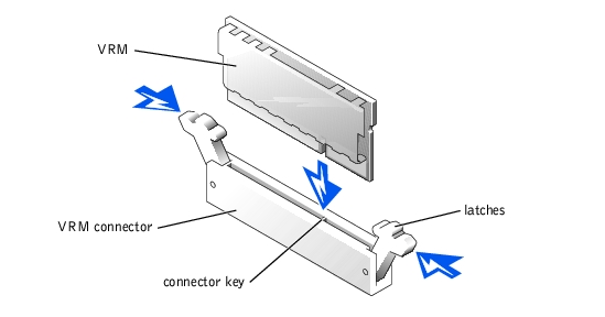
- If you are adding a second microprocessor, install the VRM in the VRM_P2 socket,
pushing down firmly to make sure that the latches engage (see Figure 6-17).
Figure 6-17. Installing the VRM
- Reinstall the cooling shroud (see "Installing the Cooling Shroud").
- Reinstall the system cover (see "Replacing the System Cover" in "Troubleshooting Your
System").
- Reconnect your system and peripherals to their electrical outlets, and turn on the
system.
- Press <F2> to enter the System Setup program, and check that the PROCESSOR 1
and PROCESSOR 2 categories match the new system configuration (see "Using the
System Setup Program" in your User's Guide).
As the system boots, it detects the presence of the new microprocessor and automatically changes the system configuration information in the System Setup program. If you installed a second microprocessor, the following message is displayed:
Two 1.8 GHZ Processors, Processor Bus: 400 MHz, L2 cache 0 KB
Advanced
If only one microprocessor is installed, the following message is displayed:
One 1.8 GHz Processor, Processor Bus: 400 MHz, L2 cache 0 KB
Advanced
- Enter the System Setup program and confirm that the top line in the system data area
correctly identifies the installed microprocessor(s) (see "Using the System Setup
Program" in your User's Guide).
- Run the system diagnostics to verify that the new microprocessor is operating
correctly.
See "Running System Diagnostics" for information on running the diagnostics and troubleshooting any problems that may occur.
The system board tray must be opened to install the RAID battery.
- Turn off the system, including any attached peripherals, and disconnect the system
from the electrical outlet.
- Remove the system cover (see "Removing the System Cover" in "Troubleshooting Your
System").
- Remove the front fan assembly (see "Replacing the Front Fan Assembly").
- Remove the cooling shroud (see "Removing the Cooling Shroud").
- Open the system board tray latch (see Figure 6-18).
Figure 6-18. Opening the System Board Tray
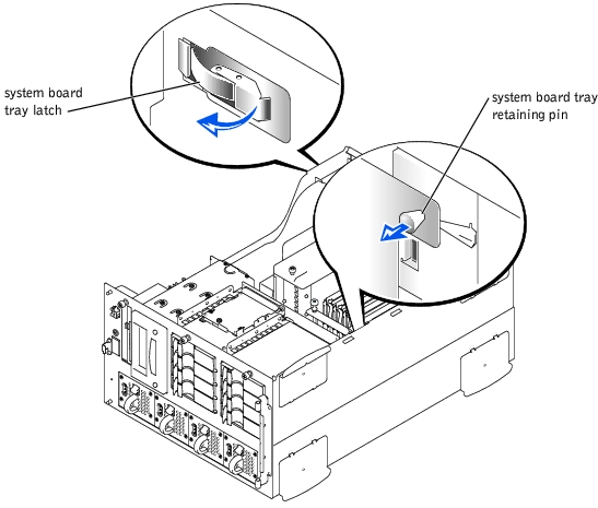
- While grasping the system board tray handle (see Figure 2-3), pull the system board
tray retaining pin (see Figure 6-18), and slide the tray out until the retaining pin locks
in the first position.
- Disconnect the following cables:
- Power distribution board power cables from system board connectors POWER 1,
POWER 2, and POWER 3 (see Figure 6-1).
- The control panel cable from the control panel mounted on the front panel.
- The intrusion switch cable from the system board.
- The interposer cable from the interposer board on the CD/diskette drives.
- Any cables from the peripheral bay, if applicable.
- Any cables connected to the system board connectors SCSI A, SCSI B, and
BACKPLANE (see Figure 6-1).
- While grasping the system board tray handle (see Figure 2-3), pull the system board
tray retaining pin (see Figure 6-18), and slide the tray out until the retaining pin locks
in the second position.
- While pulling the system board tray retaining pin, slide the tray forward until the
retaining pin locks in the first position (see Figure 6-18).
- Reconnect the following cables:
- Any cables connected to the system board connectors SCSI A, SCSI B, and
BACKPLANE (see Figure 6-1).
- Any cables to the peripheral bay, if applicable.
- The intrusion switch cable to the system board.
- The interposer cable to the interposer board on the CD/diskette drives.
- The control panel cable to the control panel mounted on the front panel.
- The power distribution board power cables to system board connectors
POWER 1, POWER 2, and POWER 3 (see Figure 6-1).
- While pulling the system board tray retaining pin, slide the tray forward until the
retaining pin locks in the second position.
- Close the system board tray locking latch (see Figure 6-18).
- Reinstall the cooling shroud (see "Installing the Cooling Shroud").
- Reinstall the front fan assembly (see "Replacing the Front Fan Assembly").
- Reinstall the cover (see "Replacing the System Cover" in "Troubleshooting Your
System").
- Reconnect the system to the electrical outlet and turn on the system, including any
attached peripherals.
|
|
CAUTION: Before you perform this procedure, you must turn off the system and
disconnect it from its power source. For more information, see "Safety First—For
You and Your System" in "Troubleshooting Your System."
|
|
NOTICE: See "Protecting Against Electrostatic Discharge" in the safety instructions in your
System Information document.
|
|
NOTICE: To avoid possible data loss, back up all data on the hard drives before changing the
mode of operation of the integrated SCSI controller from SCSI to RAID.
|
- Turn off the system, including any attached peripherals, and disconnect the system
from the electrical outlet.
- Remove the system cover (see "Removing the System Cover" in "Troubleshooting Your
System").
- Remove the cooling shroud (see "Cooling Shroud").
- Remove the memory riser cards (see "Removing the Memory Riser Cards").
- Push the ejectors on the RAID_DIMM memory module socket down and outward, as
shown in Figure 6-19, to allow the memory module to be inserted into the socket.
See Figure 6-1 for the location of the RAID memory module socket on the system board.
Figure 6-19. Installing the RAID Controller Memory Module
- Align the memory module's edge connector with the alignment keys, and insert the
memory module in the socket (see Figure 6-19).
The memory module socket has two alignment keys that allow the memory module to be installed in the socket in only one way.
|
NOTE: The RAID controller memory module must be an unbuffered memory module, rated
to run at 100 MHz or faster. Do not substitute registered memory modules such as those
used for system memory.
|
- Press on the memory module with your thumbs while pulling up on the ejectors with
your index fingers to lock the memory module into the socket.
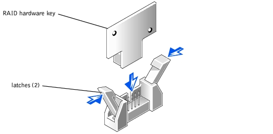
- Insert the RAID hardware key into its socket on the system board (see Figure 6-1) and
secure the key with the latches on each end of the socket (see Figure 6-20).
Figure 6-20. Installing the RAID Hardware Key
- Install the RAID battery (see steps 2 and 3 of the procedure in "Installing the RAID
Battery").
- Reinstall the memory riser cards (see "Installing the Memory Riser Cards").
- Reinstall the cooling shroud (see "Installing the Cooling Shroud").
- Reinstall the system cover.
- Reconnect the system and peripherals to their power sources and turn them on.
- Enter the System Setup program and verify that the setting for the SCSI controller has
changed to reflect the presence of the RAID hardware (see "Using the System Setup
Program" in your User's Guide).
- Install the RAID software.
See the RAID controller documentation for more information.
- Open the system board tray (see "Opening the System Board Tray").
- Hook the front edge of the battery assembly onto the slot in the bay, and then snap the
back edge of the battery assembly into place so that the battery lies flat (see Figure
6-21).
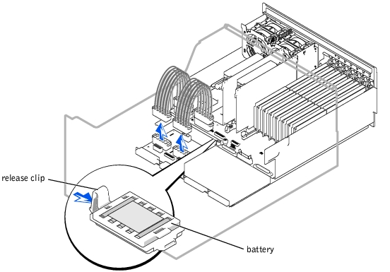
Figure 6-21. Installing the RAID Battery
- Connect the battery cable to the RAID battery connector (RAID_BAT) on the system
board (see Figure 6-1).
- Close the system board tray (see "Closing the System Board Tray").
- Open the system board tray (see "Opening the System Board Tray").
- Disconnect the battery cable from the RAID battery connector (RAID_BAT) on the
system board (see Figure 6-1).
- Press the release clip on the RAID battery and lift it straight up to clear the system (see
Figure 6-21).
- If you are replacing a RAID battery, see steps 2 and 3 of the procedure in "Installing the
RAID Battery."
- Close the system board tray (see "Closing the System Board Tray").
The system battery is a 3.0-volt (V), coin-cell battery. To replace the battery, perform the following steps.
|
|
CAUTION: Before you perform this procedure, you must turn off the system and
disconnect it from its power source. For more information, see "Safety First—For
You and Your System" in "Troubleshooting Your System."
|
|
|
CAUTION: There is a danger of a new battery exploding if it is incorrectly
installed. Replace the battery only with the same or equivalent type
recommended by the manufacturer. Discard used batteries according to the
manufacturer's instructions.
|
- Enter the System Setup program and, if possible, make a printed copy of the System
Setup screens (see "Using the System Setup Program" in the User's Guide).
- Turn off the system, including any attached peripherals, and disconnect the system
from the electrical outlet.
|
NOTICE: See "Protecting Against Electrostatic Discharge" in the safety instructions in your
System Information document.
|
- Remove the system cover (see "Removing the System Cover" in "Troubleshooting Your
System").
- Remove the system battery (see Figure 6-1 for the location).
You can pry the system battery out of its socket with your fingers or with a blunt, nonconductive object such as a plastic screwdriver.
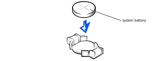
- Install the new system battery with the side labeled "+" facing up (see Figure 6-22).
Figure 6-22. Installing the System Battery
- Replace the system cover (see "Replacing the System Cover" in "Troubleshooting Your
System").
- Reconnect the system and any attached peripherals to their electrical outlets and turn
them on.
- Enter the System Setup program to confirm that the battery is operating properly (see
"Using the System Setup Program" in the User's Guide).
- Enter the correct time and date in the System Setup program's Time and Date
settings.
- Reenter any system configuration information that is no longer displayed on the
System Setup screens, and then exit the System Setup program.
- To test the newly installed battery, power down and disconnect the system from its
electrical source for at least an hour.
- After an hour, connect the system to its electrical source and turn on the power.
- Enter the System Setup program and if the time and date are still incorrect, see
"Getting Help" for instructions on obtaining technical assistance.
Back to Contents Page