Back to Contents Page
Introduction: Dell™ PowerEdge™ 8450 Systems User's Guide
Overview • System Features • Front-Panel Indicators • Connecting External Devices • Getting Help
The Dell PowerEdge 8450 system is a feature-rich, enterprise-class server
that offers the highest performance, availability, scalability, manageability, and
investment protection features. The PowerEdge 8450 provides a robust, reliable,
rack-optimized platform on which corporate customers can deploy their mission-critical
applications.
This section describes the major hardware and software features of
the computer system, provides information about the indicators on the system's front
panel, and discusses connecting external devices to the system. It also provides
information on obtaining assistance from Dell.
PowerEdge 8450 systems offer the following features:
- One to eight Intel® Pentium® III Xeon™ microprocessors with an internal operating
frequency of 500 megahertz (MHz) and an external bus speed of 100 MHz.
- A secondary (L2) cache of 1 to 2 megabytes of static random-access memory (SRAM) is
included within the single-edge contact (SEC) cartridge that contains the microprocessor.
Math coprocessor functionality is internal to the microprocessor.
- Support for symmetric multiprocessing (SMP), which is available by installing additional
microprocessors. SMP greatly improves overall system performance by dividing
microprocessor operations among the independent microprocessors. To take advantage of this
feature, you must use an operating system that supports multiprocessing, such as the
Microsoft® Windows NT® 4.0 operating system (and later versions).
 |
NOTE: If you decide to upgrade
your system by installing additional microprocessors, you must order the microprocessor
upgrade kits from Dell. Not all versions of the microprocessor will work properly as
additional microprocessors. The upgrade kit from Dell contains the correct version of the
microprocessor as well as the correct instructions for performing the upgrade. All
microprocessors must have the same internal operating frequency and cache size. |
The system's Profusion chip set architecture provides each processor
with access to the system memory and the peripheral component interconnect (PCI) bus,
using two independent processor buses and a dedicated input/output (I/O) bus, each
operating at 100 MHz.
- A minimum of 256 megabytes (MB) of system memory, upgradable to a
maximum of 32 gigabytes (GB) by installing combinations of 128-, 256-, or 512-MB or 1-GB
(when available) synchronous dynamic RAM (SDRAM) registered dual in-line memory modules
(DIMMs) in the 32 DIMM sockets on the two memory boards.
- Support for one or two 1-inch, internal, hot-pluggable, small
computer system interface (SCSI) hard-disk drives via a SCSI backplane board and special
SCSI hard-disk drive carriers. The SCSI backplane automatically configures SCSI ID numbers
and SCSI termination on individual hard-disk drives, greatly simplifying drive
installation.
- Three redundant, hot-pluggable, 750-watt (W) power supplies.
- Six redundant, hot-pluggable system cooling fans.
The system's I/O board includes the following built-in features:
- Ten hot-pluggable, 64-bit, PCI expansion-card connectors. Six of the
expansion slots operate at 33 MHz, while four operate at 66 or 33 MHz.
- A video subsystem based on the Cirrus GD5446 super video graphics
array (SVGA) video controller. This video subsystem resides on the primary PCI bus and
contains 2 MB of video memory (not upgradable). Maximum resolutions are 1024 x 768
with 256 colors noninterlaced. In 800 x 600 and 640 x 480 resolutions, 16.7
million colors are available for true-color graphics.
- An SMC FDC37C935AP super I/O controller that controls the
bidirectional parallel port, two serial ports, two Universal Serial Bus (USB) ports, the
keyboard and mouse ports, and the diskette drive in the externally accessible front bay.
- A Symbios 53C896 SCSI controller that supports two Ultra2/low voltage
differential (LVD) SCSI-3 channels.
- Server management circuitry that monitors operation of the system
fans as well as critical system voltages and temperatures. The server management circuitry
works in conjunction with the HP OpenView Network Node Manager Special Edition (NNM SE)
and the Dell OpenManage™ Hardware Instrumentation Package (HIP) software package.
- System board support for the Dell OpenManage Remote Assistant when
the optional Dell Remote Assistant Card version 2.0 (DRAC 2), which provides additional
local and remote server management, is installed.
- A basic input/output system (BIOS) that resides in 2 MB of flash
memory on the Industry-Standard Architecture (ISA) bus.
Standard PowerEdge 8450 systems include a 3.5-inch diskette drive
and an integrated drive electronics (IDE) CD-ROM drive installed in the externally
accessible bays.
The following software is included with your Dell system:
- Video drivers for displaying many popular applications in
high-resolution modes. For more information on these drivers, see Using
the Dell OpenMangage Server Assistant CD.
- HP OpenView software, including OpenView NNM SE with Dell OpenManage
HIP, a standards-based management solution that provides concise and in-depth views of
networked systems, devices, and connections through an intuitive graphical interface.
- SCSI device drivers that allow your operating system to communicate
with devices attached to the integrated SCSI subsystem. For more information on these
drivers, see Installing and Configuring SCSI Drivers.
- A system setup program for quickly viewing and changing the system
configuration information for your system. For more information on this program, see Using the System Setup Program.
- The system setup utility (SSU), which automatically configures
installed PCI expansion cards. For more information, see Using the
System Setup Utility.
- Enhanced security features, including a user password and a
supervisor password, available through the system setup program or the SSU.
- Dell Diagnostics for evaluating your system's components and devices.
For information on using the system diagnostics, see Using the Dell
OpenManage Server Assistant CD or "Running the Dell Diagnostics" in
your Installation and Troubleshooting Guide.
Supported Operating Systems
Dell supports Microsoft Windows NT Server 4.0 for use on PowerEdge
8450 systems.
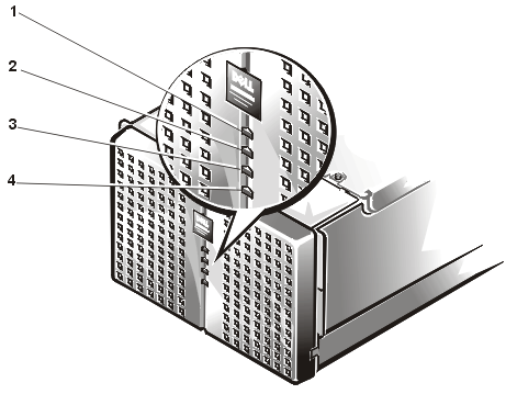
The following indicators are on the system's front panel (see Figure 1) :
- The power indicator lights green when the power supply is turned on and the system is
receiving DC power.
- The fan/temperature status indicator lights amber when a fan failure is detected or
temperature is out of bounds.
- The power-supply status indicator lights amber if a fault is detected with any of the
power supplies or any system voltages.
- The hard-disk drive fault indicator lights amber if a problem occurs with one of the
internal hard-disk drives.
Figure 1. Front Panel

1 |
Power indicator |
2 |
Fan/temperature status indicator |
3 |
Power fault indicator |
4 |
Hard-disk drive fault indicator |
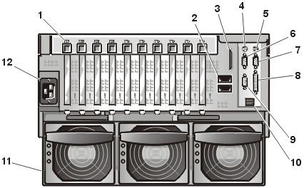
Figure 2 shows the back-panel connections on the
computer.
Figure 2. Back-Panel Features

1 |
PCI hot-plug expansion slot
indicators (10) |
2 |
Inter-chassis management bus
(ICMB) connectors (2) (when supported) |
3 |
External SCSI connector |
4 |
Keyboard connector |
5 |
Mouse connector |
6 |
Serial port B |
7 |
Serial port A |
8 |
Parallel port connector |
9 |
Video connector |
10 |
USB connectors 0 (top) and 1 |
11 |
Redundant power supplies (3) |
12 |
AC power receptacle |
When connecting external devices to the I/O ports and connectors on
the system 's back panel of your system, follow these guidelines:
- Check the documentation that accompanied the device for specific
installation and configuration instructions.
For example, most devices must be connected to a particular I/O port or connector to
operate properly. Also, external devices like a mouse or printer usually require you to
load software files called device drivers into memory before they will work. These
software drivers help the system recognize an external device and direct its operation.
Device drivers of this type are normally included with your operating system software.
- Always attach external devices while your system is turned off. Then
turn on any external devices before turning on the system unless the documentation for the
device specifies otherwise. (If the system does not seem to recognize the device, try
turning on the system before turning on the device.)
For information about enabling, disabling, or configuring I/O ports
and connectors, see Using the System Setup Program. For detailed
descriptions and illustrations of each port and connector on the I/O panel, see I/O Ports and Connectors.
If at any time you don't understand a procedure described in this
guide or if your system does not perform as expected, Dell provides a number of tools to
help you. For more information on these help tools, see "Getting Help" in your Installation
and Troubleshooting Guide.
Back to Contents Page

