Back to Contents Page
| Overview | Upgrading the Microprocessor or Installing Additional Microprocessors | ||
| Expansion Cards | Replacing the System Battery | ||
| Adding Memory |
This section describes how to install the following options:
This section also includes instructions for replacing the system battery, if necessary.
| WARNING: The power supplies in
this computer system produce high voltages and energy hazards, which can cause bodily
harm. Only trained service technicians are authorized to remove the computer cover and
access any of the components inside the computer. |
| WARNING: This system may have more than one power supply cable. To reduce the risk of electrical shock, a trained service technician must disconnect all power supply cables before servicing the system. For more information, refer to "Safety First—For You and Your Computer." |
Use Figure 1 to locate the system board features.
Figure 1. System Board Features
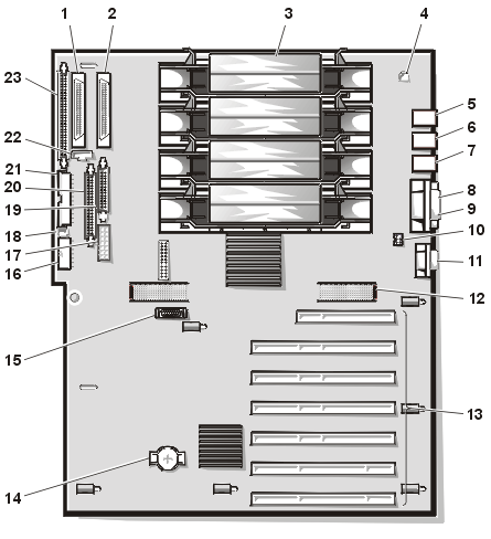
1 |
Ultra3 (Ultra160) SCSI connector (PRIMARY SCSI A) |
2 |
Ultra3 (Ultra160) SCSI connector (PRIMARY SCSI B) |
3 |
Microprocessors (PROC_1–PROC_4) |
4 |
Chassis intrusion switch connector (INTRUS1) |
5 |
Mouse (top) and keyboard (bottom) connectors |
6 |
USB connectors (2) |
7 |
NIC connector (NETWORK) |
8 |
Parallel port connector (PARALLEL) |
9 |
Serial port connectors (2) |
| 10 | Hot-plug PCI indicator board connector (PCILEDPNL) |
11 |
Video connector (VGA) |
12 |
Memory board connectors (MEMORY1 and MEMORY2) |
13 |
PCI connectors (PCI1 [top] through PCI7) |
14 |
Battery connector (BTRY) |
15 |
Dell Remote Assistant Card connector (SVR_MGT) |
16 |
Power input connector (POWER2) |
17 |
Power input connector (POWER3) |
18 |
Chassis intrusion switch connector (INTRUS2) (not used) |
19 |
SCSI backplane board interface cable connector (BACKPLANE) |
20 |
Diskette-drive interface connector (FLOPPY) |
21 |
Power input connector (POWER1) |
22 |
Fan connector (FANS) |
23 |
Ultra/Narrow SCSI connector (SECONDARY SCSI) |
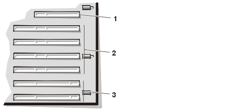
The system board contains seven Peripheral Component Interconnect (PCI) expansion-card connectors (see Figure 2).
Figure 2. Expansion-Card Connectors
 |
|
Follow these guidelines when you add an expansion card:
| NOTES: If connectors PCI6 and PCI7 are
both empty and you hot-add a 66-MHz card, the card will operate at 33 MHz until you reboot
the system. Installing a 33-MHz card in either
connector will limit the bus speed of both connectors to 33 MHz. If PCI6 or PCI7 is occupied by a card running at 66-MHz and you hot-add a 33-MHz card in the empty 66-MHz slot, you must reset the system so that the 33-MHz expansion card is activated; both cards will then run at 33-MHz. |
| NOTE: If you install a Dell OpenManage™ Remote Assistant Card (DRAC), version 2.0, you must install this expansion card in connector PCI1. |
If your computer uses the Novell® NetWare® 5.0 or Microsoft® Windows® 2000 (Release Candidate 2 or later versions) operating system, all seven expansion-card connectors support hot-plug addition and replacement of PCI expansion cards.
For systems using NetWare 5.0, the following minimum configuration
is required to support hot-plug expansion cards:
The following PCI expansion cards are supported:
(Other cards may be qualified for hot-plug operations by Dell in the future; contact Dell for current information.)
NOTICE: If you attempt hot-plug addition or replacement of an unsupported card, the system may freeze or shut down unexpectedly.
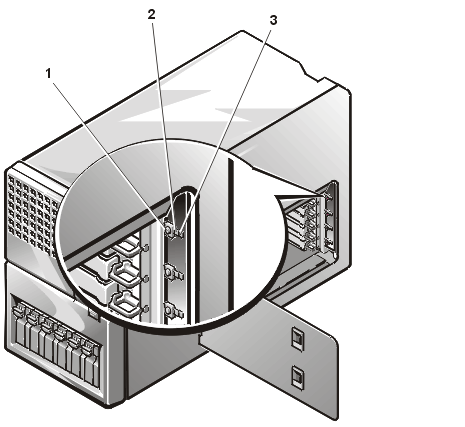
Pairs of light-emitting diodes (LEDs) adjacent to each expansion slot display each expansion-card connector's current status (see Figure 3). Table 1 lists the various codes for the hot-plug LED indicators.
| Table 1. Hot-Plug Indicator Patterns |
| Green LED | Amber LED | Safe to Remove Expansion Card? | Description |
|---|---|---|---|
| Off | Off | Yes | Connector power is off |
| On | Off | No | Connector power is on |
| Flash | Off | No | Connector is being powered up or powered down |
| Off | Flash slow | Yes | Power-up fault |
| On | Flash fast | No | Identifying a slot by user application or device driver |
Figure 3. Hot-Plug PCI Board Features
 |
|
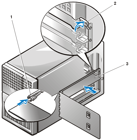
To remove an expansion card, perform the following steps.
| NOTE: To help facilitate the removal of some of the smaller PCI expansion cards (such as the Intel EtherExpress PRO/100+ NIC), card extractors are available for purchase from other suppliers. |
NOTICE: To avoid damage to the card or your computer, you must power down the expansion slot before you remove an expansion card.
- If your computer uses the NetWare 5.0 operating system, run ncmcon.nlm to place the affected slot in the off state.
NOTE: If all slots are reported with No in the Hot Plug column, press the <Esc> key to exit the ncmcon utility and ensure that dellsbd.nlm is loaded; then restart the utility by running the load ncmcon.nlm command.
- If your computer uses the Windows 2000 operating system (Release Candidate 2 or later versions), press the switch next to the expansion slot to power down the expansion-card connector, or run the Unplug or Eject Hardware control applet from the status bar.
The green LED will flash as the expansion-card connector is powered down. When both indicator lights adjacent to the expansion slot are off, the card may be safely removed.
- If your computer's operating system does not support hot-plug PCI cards, or the expansion card itself does not support hot-plug removal, shut down the system, including any attached peripherals, and disconnect the system from its electrical outlet.
Figure 4. Expansion-Card Latches
 |
|
| CAUTION: Some expansion cards can
become quite warm during system operation. Be sure that the card has had sufficient time
to cool after the connector is powered down before you touch the card. |
| NOTE: You must install a filler bracket over an empty expansion slot to maintain Federal Communications Commission (FCC) certification of the system. The brackets also keep dust and dirt out of the computer and help to maintain proper cooling and airflow inside the computer. |
To install an expansion card, perform the following steps.
NOTICE: See "Protecting Against Electrostatic Discharge."
NOTICE: You can only perform hot-plug replacement of an existing card with an identical replacement card.
NOTICE: You can hot-add a new card to a previously empty expansion slot if the card supports hot-plug installation.
NOTICE: To avoid damage to the card or your computer, you must power down the expansion slot before you install an expansion card (see step 2).
If your computer uses the NetWare 5.0 operating system, run ncmcon.nlm to place the affected slot in the off state.
| NOTE: If all slots are
reported with No in the Hot Plug column, press the
<Esc> key to exit the ncmcon utility and ensure that dellsbd.nlm
is loaded; then restart the utility by running the load ncmcon.nlm
command. |
The green LED will flash as the expansion-card connector is powered down. When both indicator lights adjacent to the expansion slot are off, the card may be safely installed.
| NOTES: If connectors PCI6 and PCI7 are
both empty and you hot-add a 66-MHz card, the card will operate at 33 MHz until you reboot
the system. Installing a 33-MHz card in either
connector will limit the bus speed of both connectors to 33 MHz. |
reinitialize system
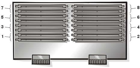
The 16 dual in-line memory module (DIMM) sockets on the memory board (see Figure 5) can accommodate 256 megabytes (MB) to 8 gigabytes (GB) of 3.3-V registered DIMMs. You can upgrade system memory to 8 GB by installing sixteen 512-MB DIMMs. You can purchase memory upgrade kits of 64-, 128- 256-, and 512-MB registered DIMMs from Dell.
| NOTE: The DIMMs must be PC133-compliant. |
The 16 DIMM sockets are arranged in four banks with four interleaved sockets per bank. When you install DIMMs, follow these guidelines:
Figure 5. DIMM Sockets
 |
|
Table 2 illustrates several sample memory configurations based on these guidelines.
| Table 2. Sample DIMM Configurations |
| DIMMs Installed | ||||
|---|---|---|---|---|
| Total Memory | 64 MB | 128 MB | 256 MB | 512 MB |
| 256 MB | 4 | |||
| 512 MB | 8 | |||
| 512 MB | 4 | |||
| 1 GB | 8 | |||
| 2 GB | 16 | |||
| 3 GB | 8 | 8 | ||
| 4 GB | 16 | |||
| 8 GB | 16 | |||
To perform a memory upgrade to the system board, perform the following steps.
| WARNING: Before you perform this procedure, you must turn off the computer and disconnect it from the electrical outlet. For more information, see "Safety First—For You and Your Computer." |
NOTICE: See "Protecting Against Electrostatic Discharge."
| NOTE: If the memory total is incorrect, turn off and disconnect the computer and peripherals from their AC power sources, remove the computer cover, and check all the installed DIMMs to make sure that they are seated properly in their sockets. Then repeat step 6. |
The system detects that the new memory does not match the system configuration information, which is stored in nonvolatile random-access memory (NVRAM). The monitor displays an error message that ends with the following words:
Press <F1> to continue; <F2> to enter System Setup
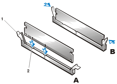
To install a DIMM, perform the following steps:
Figure 6. Installing a DIMM
 |
|
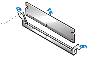
To remove a DIMM, press down and outward on the ejectors on each end of the socket until the DIMM pops out of the socket (see Figure 7).
Figure 7. Removing a DIMM
 |
|
Each microprocessor is contained within a single-edge contact (SEC) cartridge and heat sink assembly. The system board has four guide-bracket assemblies, which hold the SEC cartridge and heat sink assemblies. If your system has only one microprocessor, the remaining guide-bracket assembly connectors must contain terminator cards.
If you add additional microprocessors to the system, the microprocessors' internal operating speeds must match that of the primary microprocessor.
NOTICE: If you are upgrading a system by installing additional microprocessors, you must order an upgrade kit from Dell. The upgrade kit from Dell contains the correct version of the microprocessor for use as a secondary microprocessor.
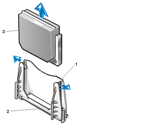
To remove a terminator card, perform the following steps.
| WARNING: Before you perform this procedure, you must turn off the computer and disconnect it from the electrical outlet. For more information, see "Safety First—For You and Your Computer." |
NOTICE: See "Protecting Against Electrostatic Discharge."
Figure 8. Removing a Terminator Card
 |
|
To install a terminator card, align the notch on the terminator card with the socket on the guide-bracket assembly and guide the card into the empty guide-bracket assembly.
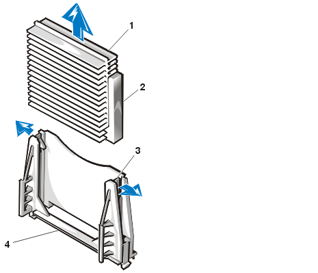
To remove the SEC cartridge and heat sink assembly, perform the following steps.
| WARNING: Before you perform this procedure, you must turn off the computer and disconnect it from the electrical outlet. For more information, see "Safety First—For You and Your Computer." |
| CAUTION: The SEC cartridge and heat sink assembly can get extremely hot during system operation. Be sure the assembly has had sufficient time to cool before you touch it. | |
| CAUTION: When handling the SEC cartridge and heat sink assembly, take care to avoid sharp edges on the heat sink. |
NOTICE: See "Protecting Against Electrostatic Discharge."
Figure 9. Removing an SEC Cartridge and Heat Sink
 |
|
To install a replacement SEC cartridge and heat sink assembly, perform the following steps:
The system battery maintains system configuration, date, and time information in a special section of memory when you turn off the system. The operating life of the battery ranges from 2 to 5 years, depending on how you use the system (for example, if you keep the system on most of the time, the battery gets little use and thus lasts longer). You may need to replace the battery if an incorrect time or date is displayed during the boot routine along with the following or similar message:
Time-of-day not set -- please run SETUP program
Strike the F1 key to continue, F2 to run the setup utility
or
System CMOS checksum bad -- Run SETUP
Strike the F1 key to continue, F2 to run the setup utility
or
Invalid configuration information -- please run SETUP program
Strike the F1 key to continue, F2 to run the setup utility
To determine if the battery needs replacing, reenter the time and date through the System Setup program. Turn off and disconnect the system from the electrical outlet for a few hours, and then reconnect and turn the system on again. Enter the System Setup program. If the date and time are not correct in the System Setup program, replace the battery.
| NOTES: Some software may cause the
system time to speed up or slow down. If the system seems to operate normally except for
the time kept in the System Setup program, the problem may be caused by software rather
than by a defective battery. If the system is turned off for long periods of time (for weeks or months), the NVRAM may lose its system configuration information. This situation is not caused by a defective battery. |
You can operate the system without a battery; however, the system configuration information maintained by the battery in NVRAM is erased each time you shut down the computer. Therefore, you must reenter the system configuration information and reset the options each time the system boots until you replace the battery.
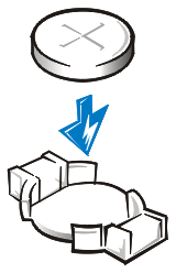
The battery is a 3.0-V, coin-cell CR2032-type battery. To remove the battery, perform the following steps.
| WARNING: Before you perform this procedure, you must turn off the computer and disconnect it from the electrical outlet. For more information, see "Safety First—For You and Your Computer." |
| CAUTION: There is a danger of a new battery exploding if it is incorrectly installed. Replace the battery only with the same or equivalent type recommended by the manufacturer. Discard used batteries according to the manufacturer’s instructions. |
NOTICE: See "Protecting Against Electrostatic Discharge."
Figure 11. Installing the Battery
 |