Back to Contents Page
Dell™ PowerEdge™ 600SC Systems
Installation and Troubleshooting Guide
If your system is not working as expected, begin troubleshooting by using the procedures in this section. This section guides you through some initial tests and procedures that can solve basic system problems and provides troubleshooting procedures for components inside the system. Before you start any of the procedures in this section, perform the following steps:

|
Read the "Safety Instructions" in your System Information Guide. |
The procedures in this guide require that you remove the cover and work inside the system. While working inside the system, do not attempt to service the system except as explained in this guide and elsewhere in your system documentation. Always follow the instructions closely. Review all of the procedures in "Safety Instructions" in your System Information Guide.
Observe the following precautions when working inside your system:
|
|
CAUTION: The power supply in this system produces high voltages and energy hazards, which can cause bodily harm. Only trained service technicians are authorized to remove the system cover and access any of the components inside the system. |
|
|
CAUTION: See "Protecting Against Electrostatic Discharge" in the safety instructions in your System Information Guide before performing any procedure that requires you to remove the cover. |
Improperly set switches, controls, and loose or improperly connected cables are the most likely source of problems for the system, monitor, or other peripherals (such as a printer, keyboard, mouse, or other external equipment). A quick check of all the switches, controls, and cable connections can easily solve many problems. See Figure 2-2 for the back-panel features and connectors.
- Turn off the system, including any attached peripherals, and disconnect the system
from the electrical outlet.
- If the system is connected to a PDU, turn the PDU off and then on again.
If the PDU is not receiving power, plug it into another electrical outlet. If it still is not receiving power, try another PDU.
- Reconnect the system to its electrical outlet or PDU and turn the system on, including
any attached peripherals.
- Is the monitor working properly?
See "Troubleshooting the Video Subsystem."
- Is the keyboard working properly?
See "Troubleshooting the Keyboard."
- Is the mouse working properly?
See "Troubleshooting the Mouse."
- Are the other attached peripherals working properly?
See "Troubleshooting the Basic I/O Functions."
Looking at and listening to the system is important in determining the source of a problem. Look and listen during the system's start-up routine for the indications described in Table 5-1.
Table 5-1. Start-Up Routine Indications
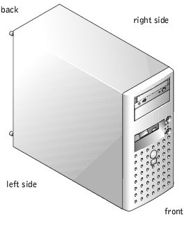
The illustrations in this document are based on the positioning of the system as shown in Figure 5-1.
Figure 5-1. System Orientation
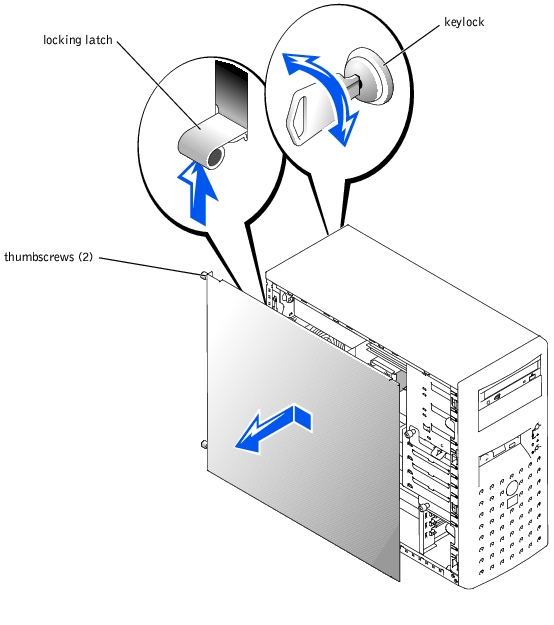
To upgrade or troubleshoot the system, remove the cover to gain access to internal components.
- Using the system key, unlock the cover (see Figure 5-2).
- Slide the cover locking latch upward.
- Loosen the two cover thumbscrews.
- Slide the cover backward and grasp it at both ends.
- Lift the cover away from the system.
Figure 5-2. Removing the Cover
 |
NOTICE: Figure 5-2 shows the system standing upright as the cover is being removed.
However, before you service components inside the system, lay the system on its right side.
|
- Ensure that no tools or loose parts are left inside the system.
- Fit the cover on the side of the system, and slide the cover forward.
- Tighten the two cover thumbscrews (see Figure 5-2).
- Slide the cover locking latch downward.
- Using the system key, lock the cover.
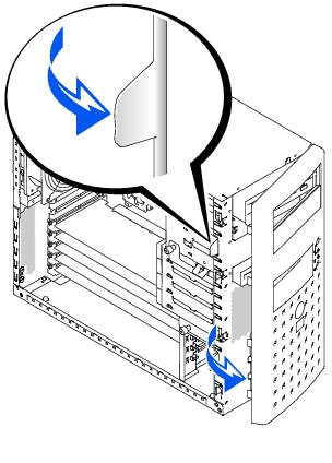
The front bezel has status and attention indicators. You must remove the cover to remove the bezel.
|
NOTICE: To remove the bezel, the system must be standing upright.
|
- Remove the cover (see "Removing the Cover").
- Pull the two levers to the left of the bezel (see Figure 5-3).
- Swing the left side of the bezel away from system, disengage the hooks at the right side
of the bezel, and lift the bezel away from the system.
Figure 5-3. Removing the Bezel
|
NOTICE: Figure 5-3 shows the system standing upright as the bezel is being removed.
However, before you service components inside the system, lay the system on its right side.
|
To install the bezel, align the hooks at the right side of the bezel, swing the left side of the bezel toward the system, and press the bezel to the system until it snaps into place.
This section provides troubleshooting procedures for equipment that connects directly to the system, such as the monitor, keyboard, or mouse. Before you perform any of the procedures, see "External Connections."
- Monitor
- Monitor interface cable
- Video memory
- Video logic
- Check the system and power connections to the monitor.
- Run the video tests in the system diagnostics (see "Running the System Diagnostics").
If the tests run successfully, the problem is not related to video hardware. Go to "Finding Software Solutions."
If the tests fail, see "Getting Help."
- System message indicates a problem with the keyboard
- Keyboard cable
- Press each key on the keyboard, and look at the keyboard and its cable for any signs of
damage.
If the keyboard appears to be free of physical damage, go to step 3.
If the keyboard is damaged, continue to step 2.
- Swap the faulty keyboard with a working keyboard.
If the problem is resolved, you must replace the faulty keyboard (see "Getting Help").
- Run the keyboard test in the system diagnostics (see "Running the System
Diagnostics").
If the test fails, see "Getting Help."
- Swap the faulty keyboard with a working keyboard.
If the problem is resolved, you must replace the faulty keyboard (see "Getting Help").
If the problem persists, see "Getting Help."
- System message indicates a problem with the mouse
- Mouse cable
- Click each button on the mouse, and look at the mouse and its cable for any signs of
damage.
If the mouse appears to be free of physical damage, go to step 3.
If the mouse is damaged, continue to step 2.
- Swap the faulty mouse with a working mouse.
If the problem is resolved, you must replace the faulty mouse (see "Getting Help").
- Run the pointing devices test in the system diagnostics (see "Running the System
Diagnostics").
If the problem is resolved, you must replace the faulty mouse (see "Getting Help").
If the test fails, see "Getting Help."
- System message indicates a problem with an I/O port
- Device connected to the port is not operating properly
- Enter the System Setup program, and check the serial port and parallel port settings
(see "Using the System Setup Program" in your User's Guide).
If the ports are enabled, go to step 3.
If the ports are not enabled, continue to step 2.
- Change the settings to enable the serial port and/or parallel port.
- Restart the system, and run the serial ports test and/or the parallel ports test in the
system diagnostics (see "Running the System Diagnostics").
If the tests fail, see "Getting Help."
If the tests run successfully but the problem persists, see one of the following procedures: "Troubleshooting a Serial I/O Device" or "Troubleshooting a Parallel Printer."
- Device connected to the serial port is not operating properly
- Serial device interface cable
- Turn off the system and any peripheral devices connected to the serial port.
- Swap the serial interface cable with a known working cable, and turn on the system
and the serial device.
If the problem is resolved, you must replace the interface cable (see "Getting Help").
- Turn off the system and the serial device, and swap the device with a comparable
device.
- Turn on the system and the serial device.
If the problem is resolved, you must replace the serial device (see "Getting Help").
If the problem persists, see "Getting Help."
- Parallel printer is not operating properly
- Parallel printer interface cable
- Turn off the system and the parallel printer.
- Swap the parallel printer interface cable with a known working cable, and turn on the
system and the printer.
- Attempt a print operation.
If the print operation is successful, you must replace the interface cable (see "Getting Help").
- Run the printer's self-test.
If the self-test fails, the printer is malfunctioning (see "Getting Help").
- System message indicates a problem with a USB device
- Device connected to a USB port is not operating properly
- USB device interface cable
- Enter the System Setup program, and ensure that the USB ports are enabled (see
"Using the System Setup Program" in your User's Guide).
- Turn off the system and any USB devices.
- Disconnect the USB devices, and connect the malfunctioning device to the other USB
connector.
- Turn on the system and the reconnected device.
If the problem is resolved, the USB connector might be defective (see "Getting Help").
- If possible, swap the interface cable with a known working cable.
If the problem is resolved, you must replace the interface cable (see "Getting Help").
- Turn off the system and the USB device, and swap the device with a comparable
device.
- Turn on the system and the USB device.
If the problem is resolved, you must replace the USB device (see "Getting Help").
If the problem persists, see "Getting Help."
- NIC cannot communicate with network
- NIC cable
- NIC, hub, and switch configuration settings
- Check the appropriate indicator on the NIC connector (see Figure 2-3).
- If the link indicator does not light, check all cable connections.
- If the activity indicator does not light, the network driver files might be damaged or deleted.
Check the drivers, and remove and reinstall the drivers if applicable. You must reboot your system for the reinstalled drivers to become active.
- Try changing the auto-negotiation setting, if possible.
- Try another connector on the switch or hub.
If you are using a NIC card instead of an integrated NIC, see the documentation for the NIC card.
- Ensure that the appropriate drivers are installed and the protocols are bound.
- Enter the System Setup program and confirm that the NICs are enabled (see "Using
the System Setup Program" in your User's Guide).
- Ensure that the NICs, hubs, and switches on the network are all set to the same data
transmission speed.
- Ensure that all network cables are of the proper type and do not exceed the maximum
length.
For more information, see "Network Cable Requirements" in your User's Guide.
Figure 5-4 shows an interior view of the system.
Figure 5-4. Inside the System
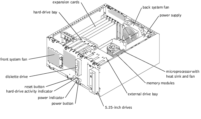
The system board contains the system's control circuitry and other electronic components. Several hardware options, such as the microprocessors and memory, are installed directly on the system board.
The system accommodates up to five full-length PCI expansion cards (one 32-bit/33-MHz card and up to four 64-bit/33-MHz cards). System memory is contained in four memory module sockets.
The system supports a 3.5-inch diskette drive and up to two externally accessible 5.25-inch drives, such as CD or tape drives. The removable hard-drive bay supports up to four 1-inch SCSI or IDE hard drives. The hard drives connect to the system board or a controller card.
During an installation or troubleshooting procedure, you may be required to change a jumper setting. For more information, see "Jumpers, Switches, and Connectors."
The optional system management applications monitor critical system voltages and temperatures, the cooling fans, and the status of hard drives in the system. Alert messages appear in the alert log window. For information about the alert log window and options, see your systems management software documentation.
- Liquid spills
- Splashes
- Excessive humidity
|
|
CAUTION: See "Protecting Against Electrostatic Discharge" in the safety instructions in your System Information Guide. |
- Turn off the system, including any attached peripherals, and disconnect the system
from the electrical outlet.
- Remove the cover (see "Removing the Cover").
- Lay the system on its right side.
- Remove all expansion cards installed in the system (see "Removing an Expansion
Card" in "Installing System Options").
- Let the system dry thoroughly for at least 24 hours.
- Stand the system upright.
- Install the cover (see "Installing the Cover").
- Reconnect the system to its electrical outlet and turn the system on, including any
attached peripherals.
If the system does not start up properly, see "Getting Help."
- If the system starts up normally, shut down the system and reinstall all of the
expansion cards you removed in step 4 (see "Installing an Expansion Card" in
"Installing System Options").
- Run the system board tests in the system diagnostics to confirm that the system is
working properly (see "Running the System Diagnostics").
If the tests fail, see "Getting Help."
- System was dropped or damaged
- Ensure that the following components are properly installed and connected:
- Expansion cards
- Power cables
- Cooling fans
- Drives
- Ensure that all cables are properly connected.
- Ensure that all components are properly installed and free from damage.
- Run the system board tests in the system diagnostics (see "Running the System
Diagnostics").
If the tests fail, see "Getting Help."
- System message indicates a problem with the battery
- System Setup program loses system configuration information
- System date and time do not stay current
The system battery maintains system configuration, date, and time information in NVRAM when you turn off the system. The operating life of the battery ranges from 2 to 5 years, depending on how you use the system (for example, if you keep the system on most of the time, the battery gets little use and thus lasts longer). You may need to replace the battery if an incorrect time or date is displayed during the boot routine.
You can operate the system without a battery; however, the system configuration information maintained by the battery in NVRAM is erased each time you remove power from the system. Therefore, you must re-enter the system configuration information and reset the options each time the system boots until you replace the battery.
- Re-enter the time and date through the System Setup program (see "Using the System
Setup Program" in your User's Guide).
- Turn off the system and disconnect it from the electrical outlet for at least one hour.
- Reconnect the system to its electrical outlet and turn the system on.
- Enter the System Setup program.
If the date and time are not correct in the System Setup program, replace the battery (see "System Battery" in "Installing System Options").
If the problem is not resolved by replacing the battery, see "Getting Help."
 |
NOTE: Some software may cause the system time to speed up or slow down. If the
system seems to operate normally except for the time kept in the System Setup
program, the problem may be caused by software rather than by a defective battery.
|
|
NOTE: If the system is turned off for long periods of time (for weeks or months), the
NVRAM may lose its system configuration information. This situation is caused by a
defective battery.
|
- Power indicator on the front panel does not light
- Systems management software issues a power supply–related message
- No power to the system
|
|
CAUTION: See "Protecting Against Electrostatic Discharge" in the safety instructions in your System Information Guide. |
- Ensure that all power cables are properly connected to the system and any attached
peripherals and to the electrical outlet (see "External Connections").
- Turn off the system, including any attached peripherals, and disconnect the system
from the electrical outlet.
- Remove the cover (see "Removing the Cover").
- Lay the system on its right side.
- Ensure that the power cables are properly connected to the power connectors on the
system board.
To identify system board connectors, see Figure A-3.
- Stand the system upright.
- Install the cover (see "Installing the Cover").
- Reconnect the system to its electrical outlet and turn the system on, including any
attached peripherals.
If the problem persists, see "Getting Help."
- Fan is not operating properly
- System message indicates a problem with cooling
- Systems management software issues a fan-related error message
- Expansion-card filler brackets are not installed over empty expansion slots
|
|
CAUTION: See "Protecting Against Electrostatic Discharge" in the safety instructions in your System Information Guide. |
- Turn off the system, including any attached peripherals, and disconnect the system
from the electrical outlet.
- Remove the cover (see "Removing the Cover").
- Lay the system on its right side.
- Ensure that the fan cables are properly connected to the fan connectors on the system
board.
To identify system board connectors, see Figure A-3.
- Ensure that expansion-card filler brackets are installed over any empty expansion slots
(see "Removing an Expansion Card" in "Installing System Options").
- Stand the system upright.
- Install the cover (see "Installing the Cover").
- Reconnect the system to its electrical outlet and turn the system on, including any
attached peripherals.
If the problem persists, replace the faulty fan (see "System Fans" in "Installing System Options").
If the problem is not resolved after a replacement fan is installed, see "Getting Help."
- Expansion card is not operating properly
- System message indicates a problem with an expansion card
- Expansion-card filler brackets are not installed over empty expansion slots
- Expansion-card cable(s)
|
|
CAUTION: See "Protecting Against Electrostatic Discharge" in the safety instructions in your System Information Guide. |
|
NOTICE: When troubleshooting an expansion card, see the documentation for your operating
system and the expansion card.
|
- Turn off the system, including any attached peripherals, and disconnect the system
from the electrical outlet.
- Remove the cover (see "Removing the Cover").
- Lay the system on its right side.
- Ensure that each expansion card is firmly seated in its connector (see "Installing an
Expansion Card" in "Installing System Options").
- Ensure that any appropriate cables are firmly connected to their corresponding
connectors on the expansion cards.
- Ensure that expansion-card filler brackets are installed over any empty expansion slots
(see "Removing an Expansion Card" in "Installing System Options").
- Stand the system upright.
- Install the cover (see "Installing the Cover").
- Reconnect the system to its electrical outlet and turn the system on, including any
attached peripherals.
- Run Quick Tests in the system diagnostics (see "Running the System Diagnostics").
If the problem persists, continue to step 11.
- Turn off the system, including any attached peripherals, and disconnect the system
from its electrical outlet.
- Remove the cover (see "Removing the Cover").
- Remove all expansion cards installed in the system (see "Removing an Expansion
Card" in "Installing System Options").
- Stand the system upright.
- Install the cover (see "Installing the Cover").
- Reconnect the system to its electrical outlet and turn the system on, including any
attached peripherals.
- Run Quick Tests in the system diagnostics (see "Running the System Diagnostics").
If the tests fail, see "Getting Help."
- For each expansion card, perform the following steps:
- Turn off the system, including any attached peripherals, and disconnect the
system from its electrical outlet.
- Remove the cover (see "Removing the Cover").
- Lay the system on its right side.
- Reinstall one of the expansion cards you removed in step 13 (see "Installing an
Expansion Card" in "Installing System Options").
- Stand the system upright.
- Install the cover (see "Installing the Cover").
- Reconnect the system to its electrical outlet and turn the system on, including any
attached peripherals.
- Run Quick Tests in the system diagnostics (see "Running the System
Diagnostics").
If the tests fail, see "Getting Help."
If you have reinstalled all of the expansion cards and the Quick Tests still fail, see "Getting Help."
- Faulty memory module
- Faulty system board
|
|
CAUTION: See "Protecting Against Electrostatic Discharge" in the safety instructions in your System Information Guide. |
- Turn on the system, including any attached peripherals.
If no error messages appear, go to step 17.
- Enter the System Setup program and check the system memory setting (see "Using
the System Setup Program" in your User's Guide).
If the amount of memory installed matches the system memory setting, go to step 17.
- Turn off the system, including any attached peripherals, and disconnect the system
from the electrical outlet.
- Remove the cover (see "Removing the Cover").
- Lay the system on its right side.
- Reseat the memory modules in their sockets (see "Installing Memory Modules" in
"Installing System Options").
- Stand the system upright.
- Install the cover (see "Installing the Cover").
- Reconnect the system to its electrical outlet and turn the system on, including any
attached peripherals.
- Enter the System Setup program and check the system memory setting (see "Using
the System Setup Program" in your User's Guide).
If the amount of memory installed does not match the system memory setting, then perform the following steps:
- Turn off the system, including any attached peripherals, and disconnect the
system from its electrical outlet.
- Remove the cover (see "Removing the Cover").
- Lay the system on its right side.
|
NOTE: There are multiple configurations for the memory modules; see "Memory Module
Installation Guidelines" in "Installing System Options." The following steps are an example
of one configuration.
|
- Swap the memory module in socket 1 with another of the same capacity (see
"Installing Memory Modules" in "Installing System Options").
- Stand the system upright.
- Install the cover (see "Installing the Cover").
- Reconnect the system to its electrical outlet and turn the system on, including any
attached peripherals.
- As the system boots, observe the monitor screen and the indicators on the keyboard.
- Perform the following steps:
- Turn off the system, including any attached peripherals, and disconnect the
system from its electrical outlet.
- Remove the cover (see "Removing the Cover").
- Repeat step 11 through step 15 for each memory module installed.
If the problem persists, see "Getting Help."
- Run the system memory test in the system diagnostics (see "Running the System
Diagnostics").
If the test fails, see "Getting Help."
- Faulty diskette
- System message indicates a problem with the diskette drive
- Diskette drive cables
|
|
CAUTION: See "Protecting Against Electrostatic Discharge" in the safety instructions in your System Information Guide. |
- Swap the diskette with a known working diskette.
If the problem is resolved, the diskette is faulty.
- Enter the System Setup program, and verify that the system is configured correctly
(see "Using the System Setup Program" in your User's Guide).
- Run the diskette drive tests in the system diagnostics to determine whether the
diskette drive operates properly (see "Running the System Diagnostics").
If the tests fail, continue to step 4.
- Turn off the system, including any attached peripherals, and disconnect the system
from the electrical outlet.
- Remove the cover (see "Removing the Cover").
- Lay the system on its right side.
- Ensure that the diskette drive interface cable is properly connected between the drive
and the system board.
To identify system board connectors, see Figure A-3.
- Ensure that a power cable is properly connected to the drive.
- Stand the system upright.
- Install the cover (see "Installing the Cover").
- Reconnect the system to its electrical outlet and turn the system on, including any
attached peripherals.
- Run the diskette drive tests in the system diagnostics to determine whether the
diskette drive operates properly (see "Running the System Diagnostics").
If the tests fail, continue to step 13.
- Turn off the system, including any attached peripherals, and disconnect the system
from its electrical outlet.
- Remove the cover (see "Removing the Cover").
- Lay the system on its right side.
- Remove all expansion cards installed in the system (see "Removing an Expansion
Card" in "Installing System Options").
- Stand the system upright.
- Install the cover (see "Installing the Cover").
- Reconnect the system to its electrical outlet and turn the system on, including any
attached peripherals.
- Run the diskette drive tests in the system diagnostics to determine whether the
diskette drive operates properly (see "Running the System Diagnostics").
If the tests complete successfully, an expansion card may be conflicting with the diskette drive, or you may have a faulty expansion card. Continue to step 21.
If the tests fail, see "Getting Help".
- For each expansion card, perform the following steps:
- Turn off the system, including any attached peripherals, and disconnect the
system from its electrical outlet.
- Remove the cover (see "Removing the Cover").
- Lay the system on its right side.
- Reinstall one of the expansion cards you removed in step 16 (see "Installing an
Expansion Card" in "Installing System Options").
- Stand the system upright.
- Install the cover (see "Installing the Cover").
- Reconnect the system to its electrical outlet and turn the system on, including any
attached peripherals.
- Run the diskette drive tests in the system diagnostics to determine whether the
diskette drive operates properly (see "Running the System Diagnostics").
If the tests fail, see "Getting Help".
If you have reinstalled all of the expansion cards and the tests still fail, see "Getting Help."
- System cannot read data from the CD
- CD drive cables
|
|
CAUTION: See "Protecting Against Electrostatic Discharge" in the safety instructions in your System Information Guide. |
- Run the IDE devices tests in the system diagnostics to determine whether the CD
drive operates properly (see "Running the System Diagnostics").
If the tests fail, continue to step 2.
- Turn off the system, including any attached peripherals, and disconnect the system
from the electrical outlet.
- Remove the cover (see "Removing the Cover").
- Lay the system on its right side.
- Ensure that the CD drive interface cable is properly connected between the drive and
the system board.
To identify system board connectors, see Figure A-3.
- Ensure that a power cable is properly connected to the drive.
- Stand the system upright.
- Install the cover (see "Installing the Cover").
- Reconnect the system to its electrical outlet and turn the system on, including any
attached peripherals.
- Run the IDE devices tests in the system diagnostics to determine whether the CD
drive operates properly (see "Running the System Diagnostics").
If the tests fail, see "Getting Help."
- Faulty tape cartridge
- Tape-drive indicator signifies a problem with the drive
- Software error
- Tape drive cables
|
|
CAUTION: See "Protecting Against Electrostatic Discharge" in the safety instructions in your System Information Guide. |
|
NOTE: If the tape-drive indicator signifies a problem with the drive, see the tape
drive's documentation for detailed information on troubleshooting.
|
- Swap the tape cartridge with a known working cartridge.
If the problem is resolved, the cartridge is faulty.
- Run the IDE devices tests in system diagnostics to determine whether the tape drive
operates properly (see "Running the System Diagnostics").
If the tests fail, continue to step 3.
- Test the tape drive by performing a tape backup and verification test (see the tape
backup software documentation).
If the tests fail, continue to step 4.
- Reinstall the tape backup software as instructed in the tape backup software
documentation.
- Turn off the system, including any attached peripherals, and disconnect the system
from the electrical outlet.
- Remove the cover (see "Removing the Cover").
- Lay the system on its right side.
- Ensure that the tape drive interface cable is properly connected between the drive and
the system board.
To identify system board connectors, see Figure A-3.
- Ensure that a power cable is properly connected to the drive.
- Stand the system upright.
- Install the cover (see "Installing the Cover").
- Reconnect the system to its electrical outlet and turn the system on, including any
attached peripherals.
- Run the IDE devices tests in the system diagnostics to determine whether the tape
drive operates properly (see "Running the System Diagnostics").
If the tests fail, see "Getting Help."
- Faulty tape cartridge
- Tape-drive indicator signifies a problem with the drive
- Software or device driver error
- Tape drive cables
|
|
CAUTION: See "Protecting Against Electrostatic Discharge" in the safety instructions in your System Information Guide. |
|
NOTE: If the tape-drive indicator signifies a problem with the drive, see the tape
drive's documentation for detailed information on troubleshooting.
|
- Swap the tape cartridge with a known working cartridge.
If the problem is resolved, the cartridge is faulty.
- Run the SCSI controllers test in the system diagnostics to determine whether the
controller operates properly (see "Running the System Diagnostics").
If the tests fail, continue to step 3.
- Ensure that any required device drivers are installed and are configured correctly. For
information on installing device drivers, see the Dell OpenManage Server Assistant CD
and the documentation that accompanied the controller card.
- Test the tape drive by performing a tape backup and verification test (see the tape
backup software documentation).
If the tests fail, continue to step 5.
- Reinstall the tape backup software as instructed in the tape backup software
documentation.
- Turn off the system, including any attached peripherals, and disconnect the system
from the electrical outlet.
- Remove the cover (see "Removing the Cover").
- Lay the system on its right side.
- Ensure that the tape drive interface cable is properly connected between the drive and
the controller card (see the documentation that accompanied the controller card).
- Ensure that a power cable is properly connected to the drive.
- Ensure that the tape drive is configured with a unique SCSI ID number and that the
drive is terminated or not terminated as appropriate.
See the documentation for the tape drive for instructions on configuring the SCSI ID and enabling or disabling termination.
- Stand the system upright.
- Install the cover (see "Installing the Cover").
- Reconnect the system to its electrical outlet and turn the system on, including any
attached peripherals.
- Test the SCSI tape drive. See the tape backup software documentation to perform a
backup and verification test.
- If the problem persists, see "Getting Help."
- Faulty hard drive
- Hard drive cables
|
|
CAUTION: See "Protecting Against Electrostatic Discharge" in the safety instructions in your System Information Guide. |
|
NOTICE: This troubleshooting procedure can destroy data stored on the hard drive. Before you
proceed, back up all the files on the hard drive.
|
- Enter the System Setup program, and verify that the system is configured correctly
(see "Using the System Setup Program" in your User's Guide).
- Run the hard drive and IDE devices tests in the system diagnostics to determine
whether the hard drive operates properly (see "Running the System Diagnostics").
If the tests fail, continue to step 3.
- Turn off the system, including any attached peripherals, and disconnect the system
from the electrical outlet.
- Remove the cover (see "Removing the Cover").
- Lay the system on its right side.
- Ensure that the hard drive interface cable is properly connected between the drive and
the system board.
To identify system board connectors, see Figure A-3.
- If the hard drive is the boot drive, ensure that the drive is configured and connected
properly (see "Configuring the Boot Drive" in "Installing Drives").
- Ensure that a power cable is properly connected to the drive.
- Stand the system upright.
- Install the cover (see "Installing the Cover").
- Reconnect the system to its electrical outlet and turn the system on, including any
attached peripherals.
- Partition and logically format the hard drive (see the operating system
documentation).
- If possible, restore the files to the drive.
If the problem persists, see "Getting Help."
- Device driver error
- Hard drive cables
- Device drivers
|
|
CAUTION: See "Protecting Against Electrostatic Discharge" in the safety instructions in your System Information Guide. |
|
NOTICE: This troubleshooting procedure can destroy data stored on the hard drive. Before you
proceed, back up all the files on the hard drive.
|
- Run the hard drive tests in the system diagnostics (see "Running the System
Diagnostics"). Also, see the RAID controller's documentation for information on
testing the controller.
If the tests fail, continue to step 2.
- Restart your system and enter the RAID configuration utility. For information on the
configuration utility, see the documentation supplied with the RAID controller card.
- Ensure that any required device drivers are installed and are configured correctly. For
information on installing device drivers, see the Dell OpenManage Server Assistant CD
and the documentation that accompanied the controller card.
- Turn off the system, including any attached peripherals, and disconnect the system
from the electrical outlet.
- Remove the cover (see "Removing the Cover").
- Lay the system on its right side.
- Ensure that the hard drive interface cable is properly connected between the drive and
the controller card (see the documentation that accompanied the controller card).
- If the hard drive is the boot drive, ensure that the drive is configured and connected
properly (see "Configuring the Boot Drive" in "Installing Drives").
- Ensure that a power cable is properly connected to the drive.
- Stand the system upright.
- Install the cover (see "Installing the Cover").
- Reconnect the system to its electrical outlet and turn the system on, including any
attached peripherals.
If the problem persists, continue to step 13.
- Partition and logically format the hard drive (see the operating system
documentation).
- If possible, restore the files to the drive.
If the problem persists, see "Getting Help."
- Device driver error
- Hard drive cables
- Device drivers
|
|
CAUTION: See "Protecting Against Electrostatic Discharge" in the safety instructions in your System Information Guide. |
|
NOTICE: This troubleshooting procedure can destroy data stored on the hard drive. Before you
proceed, back up all the files on the hard drive.
|
- Run the SCSI controllers test and the hard drive tests in the system diagnostics (see
"Running the System Diagnostics"). Also, see the SCSI or RAID controller's
documentation for information on testing the controller.
If the tests fail, continue to step 2.
- Restart your system and enter the SCSI configuration utility. For information on the
configuration utility, see the documentation supplied with the SCSI or RAID
controller card.
- Ensure that the primary SCSI channel is enabled, and restart the system (see the
documentation for your SCSI or RAID controller).
- Ensure that any required device drivers are installed and are configured correctly. For
information on installing device drivers, see the Dell OpenManage Server Assistant CD
and the documentation that accompanied the controller card.
- Turn off the system, including any attached peripherals, and disconnect the system
from the electrical outlet.
- Remove the cover (see "Removing the Cover").
- Lay the system on its right side.
- Ensure that the hard-drive interface cable is properly connected between the drive and
the controller card (see the documentation that accompanied the controller card).
- If the hard drive is the boot drive, ensure that the drive is configured and connected
properly (see "Configuring the Boot Drive" in "Installing Drives").
- Ensure that a power cable is properly connected to the drive.
- Ensure that the hard drive is configured with a unique SCSI ID number and that the
drive is terminated or not terminated as appropriate.
See the documentation for the hard drive for instructions on configuring the SCSI ID and enabling or disabling termination.
- Stand the system upright.
- Install the cover (see "Installing the Cover").
- Reconnect the system to its electrical outlet and turn the system on, including any
attached peripherals.
If the problem persists, continue to step 15.
- Partition and logically format the hard drive (see the operating system
documentation).
- If possible, restore the files to the drive.
If the problem persists, see "Getting Help."
Your system may contain an optional RAID controller card. If you encounter problems with a controller, see the RAID controller's documentation for detailed information on troubleshooting.
- System message indicates a problem with the microprocessor
- Heat sink is not installed for the microprocessor
- Fan is not operating properly
|
|
CAUTION: See "Protecting Against Electrostatic Discharge" in the safety instructions in your System Information Guide. |
- Turn off the system, including any attached peripherals, and disconnect the system
from the electrical outlet.
- Remove the cover (see "Removing the Cover").
- Lay the system on its right side.
- Ensure that the microprocessor and heat sink with cooling fan are properly installed
(see "Replacing the Microprocessor" in "Installing System Options").
- Stand the system upright.
- Install the cover (see "Installing the Cover").
- Reconnect the system to its electrical outlet and turn the system on, including any
attached peripherals.
- Run Quick Tests in the system diagnostics (see "Running the System Diagnostics").
If the tests fail or the problem persists, see "Getting Help."
- System message indicates a problem with the system board
|
|
CAUTION: See "Protecting Against Electrostatic Discharge" in the safety instructions in your System Information Guide. |
- Turn off the system, including any attached peripherals, and disconnect the system
from the electrical outlet.
- Remove the cover (see "Removing the Cover").
- Lay the system on its right side.
- Remove all expansion cards installed in the system (see "Removing an Expansion
Card" in "Installing System Options").
|
NOTE: If the boot drive is connected to a SCSI or RAID controller card, remove all
expansion cards except the controller card used by the boot drive.
|
- Stand the system upright.
- Install the cover (see "Installing the Cover").
- Reconnect the system to its electrical outlet and turn the system on, including any
attached peripherals.
- Run Quick Tests in the system diagnostics (see "Running the System Diagnostics").
If the tests fail, see "Getting Help."
- For each expansion card, perform the following steps:
- Turn off the system, including any attached peripherals, and disconnect the
system from its electrical outlet.
- Remove the cover (see "Removing the Cover").
- Lay the system on its right side.
- Reinstall one of the expansion cards you removed in step 4 (see "Installing an
Expansion Card" in "Installing System Options").
- Stand the system upright.
- Install the cover (see "Installing the Cover").
- Reconnect the system to its electrical outlet and turn the system on, including any
attached peripherals.
- Run Quick Tests in the system diagnostics (see "Running the System
Diagnostics").
If the tests fail, see "Getting Help."
If you have reinstalled all of the expansion cards and the Quick Tests still fail, see "Getting Help."
If your system cannot boot and you have exhausted all other troubleshooting options, perform the following steps.
|
|
CAUTION: See "Protecting Against Electrostatic Discharge" in the safety instructions in your System Information Guide. |
|
NOTICE: After you reset the configuration settings using the NVRAM_CLR jumper, you must
enter the System Setup program and restore any option settings that were not in your default
configuration. For more information, see "Using the System Setup Program" in your User's
Guide.
|
- Turn off the system, including any attached peripherals, and disconnect the system
from the electrical outlet.
- Remove the cover (see "Removing the Cover").
- Lay the system on its right side.
- Install the NVRAM_CLR jumper.
See Figure A-2 to locate the jumper on the system board.
|
NOTICE: When the jumper plug is installed on both pins of the NVRAM_CLR jumper block,
the configuration settings will be cleared during the next system startup.
|
- Stand the system upright.
- Install the cover (see "Installing the Cover").
- Reconnect the system to its electrical outlet and turn the system on, including any
attached peripherals.
|
NOTE: The configuration settings have been cleared.
|
- Turn off the system, including any attached peripherals, and disconnect the system
from the electrical outlet.
- Remove the cover (see "Removing the Cover").
- Lay the system on its right side.
- Remove the NVRAM_CLR jumper.
See Figure A-2 to locate the jumper on the system board.
|
NOTE: You can store a spare, unused jumper plug on one pin of the NVRAM_CLR jumper
block.
|
- Stand the system upright.
- Install the cover (see "Installing the Cover").
- Reconnect the system to its electrical outlet and turn the system on, including any
attached peripherals.
- Enter the System Setup program, and change the configuration settings appropriate
for your system (see "Using the System Setup Program" in your User's Guide).
- Reboot the system.
If the problem persists, see "Getting Help."
- Enter the System Setup program and restore any option settings that were not in your
default configuration. For more information, see "Using the System Setup Program" in
your User's Guide.
Back to Contents Page
 Safety First—For You and Your System