 System-Status Indicators
Dell™ PowerEdge™ 2650 Systems Installation and Troubleshooting Guide
System Identification Indicators
Front-Panel Indicators and Features
Back-Panel Indicators and Features
SCSI Hard-Drive Indicator Codes
Applications, operating systems, and the system itself are capable of identifying problems and alerting you to them. When a problem occurs, a message may appear on the monitor or front-panel status LCD, or a beep code may sound.
A variety of messages and codes can indicate when the system is not functioning properly:
The system indicators and features are illustrated in Figure 2-1 through Figure 2-6. This section also describes each type of message, and lists the possible causes and actions you can take to resolve any problems indicated by a message. To determine what type of message you have received, read the following subsections.
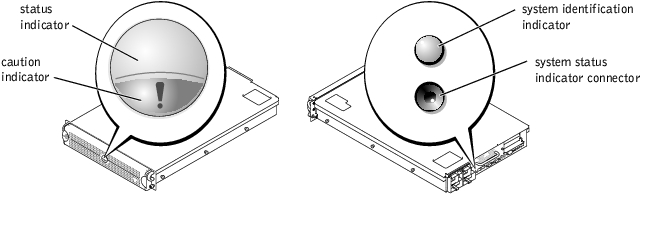
The system's bezel has an indictor that can represent system status when the bezel is installed (see Figure 2-1). The indicator signifies when the system is operating properly or when the system needs attention. The back-panel indicator functions the same as the bezel indicator. The back-panel indicator connector allows an indicator to be attached that will also function the same as the bezel indicator (see Figure 2-3).
A caution code signifies a problem with microprocessors, power supply, system or power-supply fans, system temperature, hard drives, system memory, expansion cards, or integrated SCSI controller.
Table 2-1 lists the system's status indicator codes.
Figure 2-1. System-Status Indicators
|
Bezel Indicators |
Back-Panel Indicators |
Indicator Code | |
|---|---|---|---|
|
Status |
Caution | ||
Off | Off | Off | No power is available to the system, or the system is not powered on. |
On | Off | Blue | The system is operating normally. |
Off | Blinking | Amber blinking | The system has detected an error and requires attention. |
Blinking | Off | Blue blinking | The system is identifying itself (see "System Identification Indicators"). |
The identification buttons on the front and back panels can be used to identify a particular system within a rack. See Figure 2-2 to locate the front-panel system identification button. See Figure 2-3 to locate the back-panel system identification button and indicator.
When either of the identification buttons is pushed, the identification indicator on the back blinks until one of the buttons is pushed again. If the bezel is installed, the system status indicator will also blink. If an indicator is connected to the back-panel system status indicator connector, that indicator will also blink.
Systems management software can also be used to cause the status and identification indicators to blink to identify a particular system. For more information, see the systems management software documentation.
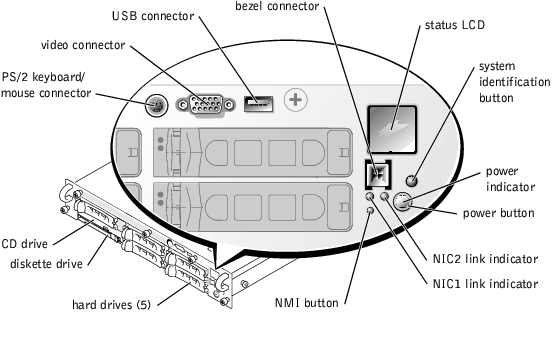
Additional indicators are located behind the bezel. The front-panel status LCD provides information using an alphanumeric character display (see "LCD Status Messages"). See Figure 2-2 for the front-panel indicators and features.
Figure 2-2 shows the front-panel features of the system. Table 2-2 describes the front-panel features.
Figure 2-2. Front-Panel Features
|
Component |
Description |
|---|---|
Power button | Turns system power off and on.
The button is enabled in the System Setup program. When disabled, the button can only turn system power on. For more information, see the User's Guide and the operating system's documentation. |
Power indicator | Provides information on power status (see "Power Indicator Codes"). |
CD and diskette drive indicators | Indicates read or write access to the respective drive. |
hard-drive indicators | Provide information on the status of the respective hard drive (see "SCSI Hard-Drive Indicator Codes"). |
NIC indicators | Indicate whether the NIC has a valid link to the network (see "NIC Indicator Codes"). |
Status LCD | Can signify when the system is operating correctly or when the system needs attention (see "LCD Status Messages"). |
System identification button | Can be used to identify a particular system (see "System Identification Indicators"). |
NMI button | Can be used to troubleshoot software and device driver errors when using certain operating systems. This button is often referred to as a "force dump switch" and can be pressed using the end of a paper clip. When the option is enabled in the System Setup program and the button is pressed, an NMI alerts the system. Use this button only if directed to do so by qualified support personnel or by the operating system's documentation. For more information, see the User's Guide and the operating system's documentation. |
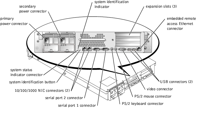
Figure 2-3 shows the back-panel features of the system. Table 2-3 describes the back-panel features.
Figure 2-3. Back-Panel Features
|
Component |
Description |
|---|---|
Power supply indicators | Provides information on power status (see "Power Indicator Codes"). |
NIC indicators | Provides information on NIC status (see "NIC Indicator Codes"). |
System status indicator connector | Connects to an indicator that can signify when the system is operating correctly or when the system needs attention (see "System-Status Indicators"). |
System identification indicator | Signifies when the system is operating correctly or when the system needs attention, and can identify a particular system (see "System Identification Indicators"). |
System identification button | Can be used to identify a particular system (see "System Identification Indicators"). |
The system has indicators on the front panel and the power supplies that signify system power status.
The power button controls the power input to the system's power supplies. The power button indicator can provide information on power status (see Figure 2-2).
Table 2-4 lists the power button indicator codes.
|
Indicator |
Indicator Code |
|---|---|
On | Indicates that power is supplied to the system, and the system is operational. |
Off | Indicates that no power is supplied to the system. |
Blinking | Indicates that power is supplied to the system, but the system is in a standby state. For more information on standby states, see your operating system documentation. |
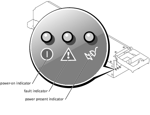
Each hot-pluggable power supply has indicators that can provide information on power status, fault, and the presence of power (see Figure 2-4). Table 2-5 lists the power-supply indicator codes.
Figure 2-4. Power-Supply Indicators
|
Indicator |
Indicator Code |
|---|---|
Power-on | Green indicates that the power supply is operational. |
Fault | Red indicates a problem with the power supply (fan failure, voltage error, etc.). |
Power present | Green indicates that power is present at the power supply and that the system is connected to a power source. |
Each SCSI hard-drive carrier has two indicators: a busy indicator and a status indicator (see Figure 2-5). The indicators provide information on the status of the respective hard drive. Table 2-6 lists the drive indicator codes.
Figure 2-5. SCSI Hard-Drive Indicators
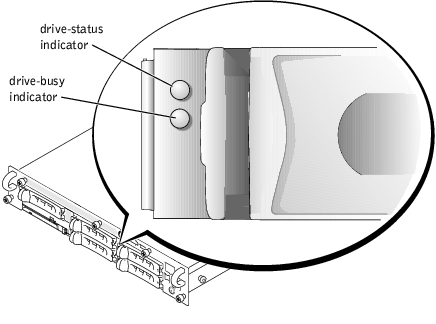
Table 2-6 lists the drive indicator codes. Different codes display as drive events occur in the system. For example, in the event of a hard-drive failure, the "drive fail" code appears. After the drive is selected for removal, the "preparing for removal" code appears. After the replacement drive is installed, the "preparing for operation, drive online" code appears.
|
Drive Status Indicator |
Indicator Code |
|---|---|
Drive bay empty, ready for insertion or removal | Off |
Drive being prepared for operation, drive online | Steady green |
Drive being identified | Blinks green four times per second |
Drive being prepared for removal | Blinks green twice per second at equal intervals |
Drive rebuilding | Blinks green twice per second at unequal intervals |
Drive failed | Blinks amber four times per second |
Predicted failure for the drive | Blinks green, then amber, and then off, repeating this sequence every two seconds |
NOTE: The drive busy indicator signifies whether the hard drive is active on the SCSI bus. This indicator is controlled by the hard drive. | |
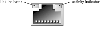
Each NIC on the back panel has an indicator that provides information on network activity and link status (see Figure 2-6). Table 2-7 lists the NIC indicator codes on the back panel.
The front panel has a link indicator for each NIC (see Figure 2-2). Each indicator signifies whether the corresponding NIC is connected to a valid link partner on the network.
|
Indicator |
Indicator Code |
|---|---|
Link and activity indicators are off | The NIC is not connected to the network. |
Link indicator is green | The NIC is connected to a valid link partner on the network. |
Activity indicator is amber blinking | Network data is being sent or received. |
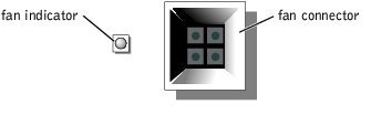
Each individual fan has a status indicator on the system board adjacent to the respective fan's connector (see Figure 2-7). To locate the fan connectors on the system board, see Figure A-3. Table 2-8 lists the fan indicator codes.
Figure 2-7. Cooling Fan Indicators
|
Indicator |
Indicator Code |
|---|---|
Off | The fan is not installed. |
Green | The fan is operating normally. |
Amber blinking | The fan is malfunctioning. |
The system's bezel indictor can signify when the system is operating correctly or when the system needs attention (see Figure 2-1). When the bezel indicator signifies an error condition, remove the bezel to see further information provided by the status LCD.
The LCD can display two lines of alphanumeric characters. The display codes are presented in two color combinations:
Table 2-9 lists the LCD status messages that can occur and the probable cause for each message. The LCD messages refer to events recorded in the SEL. For information on the SEL and configuring system management settings, see the systems management software documentation.
 |
NOTE: Before you perform any procedures described in Table 2-9, see "Before You Begin" in "Troubleshooting Your System." |
|
Line 1 |
Line 2 |
Causes |
Corrective Actions |
|---|---|---|---|
SYSTEM ID | SYSTEM NAME | SYSTEM ID is a unique name, five characters or less, defined by the user. SYSTEM NAME is a unique name, 16 characters or less, defined by the user. The system ID and name display under the following conditions:
| This message is for information only. You can change the system ID and name in the System Setup program. See your system's User's Guide for instructions. |
E0000 | OVRFLW CHECK LOG | LCD overflow message. A maximum of three error messages can display sequentially on the LCD. The fourth message displays as the standard overflow message. | Check the SEL for details on the events. |
E0119 | TEMP AMBIENT | Ambient system temperature is out of acceptable range. | See "Troubleshooting System Cooling" in "Troubleshooting Your System." |
E0119 | TEMP BP | Backplane board is out of acceptable temperature range. | |
E0119 | TEMP CPU n | Specified microprocessor is out of acceptable temperature range. | See "Troubleshooting System Cooling" in "Troubleshooting Your System." If the problem persists, ensure that the microprocessor heat sinks are properly installed (see "Adding or Replacing a Microprocessor" in "Installing System Options"). |
E0119 | TEMP SYSTEM | System board is out of acceptable temperature range. | See "Troubleshooting System Cooling" in "Troubleshooting Your System." |
E0212 | VOLT 3.3 | System power supply is out of acceptable voltage range; faulty or improperly installed power supply. | See "Troubleshooting Power Supplies" in "Troubleshooting Your System." |
E0212 | VOLT 5 | ||
E0212 | VOLT 12 | ||
E0212 | VOLT BATT | Faulty battery; faulty system board. | See "Troubleshooting the System Battery" in "Troubleshooting Your System." |
E0212 | VOLT BP 12 | Backplane board is out of acceptable voltage range. | Ensure that the power cables are securely connected to the backplane board (see "Installing Drives"). If the problem persists, see "Troubleshooting Power Supplies" in "Troubleshooting Your System." |
E0212 | VOLT BP 3.3 | ||
E0212 | VOLT BP 5 | ||
E0212 | VOLT CPU VRM | Microprocessor VRM voltage is out of acceptable range; faulty or improperly installed microprocessor VRM; faulty system board. | Ensure that supported VRMs of the same type are properly installed. If the problem persists, replace the VRMs (see Figure 6-9). If the problem persists, see "Getting Help." |
E0212 | VOLT NIC 1.8V | Integrated NIC voltage is out of acceptable range; faulty or improperly installed power supply; faulty system board. | See "Troubleshooting Power Supplies" in "Troubleshooting Your System." |
E0212 | VOLT NIC 2.5V | ||
E0212 | VOLT PLANAR REG | System board is out of acceptable voltage range; faulty or improperly installed system board. | |
E0276 | CPU VRM n | Specified microprocessor VRM is faulty, unsupported, improperly installed, or missing. | Ensure that supported VRMs of the same type are properly installed. If the problem persists, replace the VRM (see Figure 6-9 in "Installing System Options"). |
E0276 | MISMATCH VRM n | ||
E0280 | MISSING VRM n | ||
E0319 | PCI OVER CURRENT | Faulty or improperly installed expansion card. | See "Troubleshooting Expansion Cards" in "Troubleshooting Your System." |
E0412 | RPM FAN n | Specified cooling fan is faulty, improperly installed, or missing. | See "Troubleshooting a Cooling Fan" in "Troubleshooting Your System." |
E0780 | MISSING CPU 1 | Microprocessor is not installed in socket 1. | Install a microprocessor in socket 1 (see "Adding or Replacing a Microprocessor" in "Installing System Options"). To identify microprocessor socket 1, see Figure A-3. |
E07F0 | CPU IERR | Faulty or improperly installed microprocessor. | See "Troubleshooting a Microprocessor" in "Troubleshooting Your System." |
E07F1 | TEMP CPU n HOT | Specified microprocessor is out of acceptable temperature range and has halted operation. | See "Troubleshooting System Cooling" in "Troubleshooting Your System." If the problem persists, ensure that the microprocessor heat sinks are properly installed (see "Adding or Replacing a Microprocessor" in "Installing System Options"). |
E07F4 | POST CACHE | Faulty or improperly installed microprocessor. | See "Troubleshooting a Microprocessor" in "Troubleshooting Your System." |
E07F4 | POST CPU REG | ||
E07F4 | POST CPU SMI | SMI handler failed to initialize; faulty system board. | See "Getting Help." |
E07FA | TEMP CPU n THERM | Specified microprocessor is out of acceptable temperature range and is operating at a reduced speed, or frequency. | See "Troubleshooting System Cooling" in "Troubleshooting Your System." If the problem persists, ensure that the microprocessor heat sinks are properly installed (see "Adding or Replacing a Microprocessor" in "Installing System Options"). |
E0876 | POWER PS n | No power available from the specified power supply; specified power supply is improperly installed or faulty. | See "Troubleshooting Power Supplies" in "Troubleshooting Your System." |
E0880 | INSUFFICIENT PS | Insufficient power is being supplied to the system; power supplies are improperly installed, faulty, or missing. | See "Troubleshooting Power Supplies" in "Troubleshooting Your System." |
E0CB2 | MEM SPARE ROW | Correctable errors threshold was met in a memory bank: errors were remapped to the spare row. | See "Troubleshooting System Memory" in "Troubleshooting Your System." |
E0CF1 | MBE DIMM Bank n | Memory modules installed in the specified bank are not the same type and size; faulty memory module(s). | Ensure that all banks contain memory modules of the same type and size and that they are properly installed. If the problem persists, see "Troubleshooting System Memory" in "Troubleshooting Your System." |
E0CF1 | POST MEM 64K | Parity failure in the first 64 KB of main memory. | See "Troubleshooting System Memory" in "Troubleshooting Your System." |
E0CF1 | POST NO MEMORY | Main-memory refresh verification failure. | Ensure that all banks contain memory modules of the same type and size and that they are properly installed. If the problem persists, see "Troubleshooting System Memory" in "Troubleshooting Your System." |
E0CF5 | LOG DISABLE SBE | Multiple single-bit errors on a single memory module. | See "Troubleshooting System Memory" in "Troubleshooting Your System." |
E0D76 | DRIVE FAIL | Faulty or improperly installed hard drive or RAID controller. | See "Troubleshooting Hard Drives" and "Troubleshooting a RAID Controller Card" in "Troubleshooting Your System." |
E0F04 | POST CMOS | CMOS write/read failure; faulty system board. | See "Getting Help." |
E0F04 | POST CPU SPEED | Microprocessor speed control sequence failure. | See "Getting Help." |
E0F04 | POST DMA INIT | DMA initialization failure; DMA page register write/read failure. | See "Troubleshooting System Memory" in "Troubleshooting Your System." |
E0F04 | POST DMA REG | Faulty system board. | See "Getting Help." |
E0F04 | POST KYB CNTRL | Faulty keyboard controller; faulty system board. | See "Getting Help." |
E0F04 | POST MEM RFSH | Main-memory refresh verification failure. | See "Troubleshooting System Memory" in "Troubleshooting Your System." |
E0F04 | POST PIC REG | Master or slave PIC register test failure. | See "Getting Help." |
E0F04 | POST SHADOW | BIOS-shadowing failure. | See "Troubleshooting System Memory" in "Troubleshooting Your System." |
E0F04 | POST SHD TEST | Shutdown test failure. | |
E0F04 | POST SIO | Super I/O chip failure; faulty system board. | See "Getting Help." |
E0F04 | POST TIMER | Programmable interval timer test failure; faulty system board. | See "Getting Help." |
E0F0B | POST ROM CHKSUM | Faulty or improperly installed expansion card. | See "Troubleshooting Expansion Cards" in "Troubleshooting Your System." |
E0F0C | VID MATCH CPU n | Specified microprocessor is faulty, unsupported, improperly installed, or missing. | See "Troubleshooting a Microprocessor" in "Troubleshooting Your System." |
E10F3 | LOG DISABLE BIOS | BIOS disabled logging errors. | Check the SEL for details on the errors. |
E13F2 | IO CHANNEL CHECK | Faulty or improperly installed expansion card; faulty system board. | See "Troubleshooting Expansion Cards" in "Troubleshooting Your System." |
E13F4 | PCI PARITY | ||
E13F5 | PCI SYSTEM | ||
E13F8 | CPU BUS INIT | Faulty or improperly installed microprocessor or system board. | See "Troubleshooting a Microprocessor" in "Troubleshooting Your System." If the problem persists, see "Getting Help." |
E13F8 | CPU BUS PARITY | Faulty system board. | See "Getting Help." |
E13F8 | CPU MCKERR | Machine check error; faulty or improperly installed microprocessor; faulty system board. | See "Troubleshooting a Microprocessor" in "Troubleshooting Your System." |
E13F8 | HOST BUS | Faulty system board. | See "Getting Help." |
E13F8 | HOST TO PCI BUS | ||
E13F8 | MEM CONTROLLER | Faulty or improperly installed memory module; faulty system board. | See "Troubleshooting System Memory" in "Troubleshooting Your System." |
E1580 | POWER CONTROL | Faulty system board. | See "Getting Help." |
E20F1 | OS HANG | Operating system watchdog timer timed out. | Restart your system. If the problem persists, see your operating system documentation. |
EFFF0 | RAC ERROR | Remote access controller firmware failure; faulty system board. | See "Getting Help." |
EFFF1 | POST ERROR | BIOS error. | Update the BIOS firmware (see "Getting Help"). |
EFFF2 | BP ERROR | Faulty or improperly installed backplane board. | Ensure that the interface cables are securely connected to the backplane board (see "Installing Drives"). If the problem persists, see "Getting Help." |
NOTE: For the full name of an abbreviation or acronym used in this table, see "Abbreviations and Acronyms." | |||
When a single message appears on the status LCD, locate the code in Table 2-9 and perform the suggested corrective action. The code on the LCD can often specify a very precise fault condition that is easily corrected. For example, if the code E0280 MISSING VRM 2 appears, you know that a microprocessor is installed in socket 2, but the VRM for that microprocessor is either improperly installed or missing.
In contrast, you might be able to determine the problem if multiple related errors occur. For example, if you receive a series of messages indicating multiple voltage faults, you might determine that the problem is a failing power supply.
For faults associated with sensors, such as temperature, voltage, fans, and so on, the LCD message is automatically removed when that sensor returns to a normal state. For example, if temperature for a component goes out of range, the LCD displays the fault; when the temperature returns to the acceptable range, the message is removed from the LCD. For other faults, you must take action to remove the message from the display:
Any of these actions will remove fault messages, and return the status indicators and LCD colors to the normal state. Messages will reappear under the following conditions:
System messages appear on the console during POST to notify you of a possible problem with the system. If you are performing console redirection, system messages will appear on the remote console. Table 2-10 lists the system messages that can occur and the probable cause for each message.
|
NOTE: If you receive a system message that is not listed in Table 2-10, check the documentation for the application program that is running when the message appears or the operating system's documentation for an explanation of the message and recommended action. |
|
NOTE: Before you perform any procedures described in Table 2-10, see "Before You Begin" in "Troubleshooting Your System." |
|
Message |
Causes |
Corrective Actions |
|---|---|---|
Address mark not found | Faulty CD/diskette drive subsystem or hard-drive subsystem; faulty system board. | See "Troubleshooting the Diskette Drive," "Troubleshooting a CD Drive," and "Troubleshooting Hard Drives" in "Troubleshooting Your System." |
Alert! Current configuration does not support redundant memory. Redundant memory is disabled. | Memory modules installed are not the same type and size in all banks; faulty memory module(s). | Ensure that all banks contain memory modules of the same type and size and that they are properly installed. If the problem persists, see "Troubleshooting System Memory" in "Troubleshooting Your System." |
Alert! Unsupported memory or incomplete sets in the following bank(s): Bank x | Memory modules installed in the specified bank are not the same type and size; faulty memory module(s). | Ensure that all banks contain memory modules of the same type and size and that they are properly installed. If the problem persists, see "Troubleshooting System Memory" in "Troubleshooting Your System." |
Amount of available memory limited to 256 MB! | OS Install Mode is enabled in the System Setup program. | Disable OS Install Mode in the System Setup program (see "Using the System Setup program" in the User's Guide). |
Auxiliary device failure | Loose or improperly connected mouse or keyboard cable; faulty mouse or keyboard. | See "Troubleshooting the Mouse" and "Troubleshooting the Keyboard" in "Troubleshooting Your System." |
BIOS Update Attempt Failed! | Remote BIOS update attempt failed. | Retry the BIOS update. If problem persists, see "Getting Help." |
CD-ROM drive not found | Improperly connected or missing CD drive. | See "Troubleshooting a CD Drive" in "Troubleshooting Your System." |
CPUs with different cache sizes detected | Microprocessors with different cache sizes are installed. | Ensure that all microprocessors have the same cache size and that they are properly installed (see "Adding or Replacing a Microprocessor" in "Installing System Options"). |
Decreasing available memory | Faulty or improperly installed memory modules. | See "Troubleshooting System Memory" in "Troubleshooting Your System." |
Diskette drive n seek failure | Incorrect configuration settings in the System Setup program. | Run the System Setup program to correct the settings (see "Using the System Setup Program" in the User's Guide). |
Faulty or improperly installed diskette drive. | See "Troubleshooting the Diskette Drive" in "Troubleshooting Your System." | |
Diskette read failure | Faulty or improperly inserted diskette. | Replace the diskette. |
Diskette subsystem reset failed | Faulty or improperly installed diskette drive. | See "Troubleshooting the Diskette Drive" in "Troubleshooting Your System." |
ECC memory error | Faulty or improperly installed memory modules. | See "Troubleshooting System Memory" in "Troubleshooting Your System." |
Remote access controller error | Embedded remote access memory may be temporarily corrupted. | To clear the embedded remote access memory, shut down the system, disconnect the power cords, wait approximately 30 seconds, reconnect the power cords, and restart the system. If the problem persists, see "Getting Help." |
Remote access controller is not present | ||
Error: Maximum PCI option ROM count exceeded! | Too many expansion cards have ROM enabled in the System Setup program. | Disable ROM for some of the expansion cards. See "Using the System Setup Program" in the User's Guide. |
Gate A20 failure | Faulty keyboard controller; faulty system board. | See "Getting Help." |
Hard disk controller failure | Incorrect configuration settings in System Setup program; improperly installed hard drive, or loose interface or power cable; faulty hard-drive controller subsystem. | Run the System Setup program to correct the drive type (see "Using the System Setup Program" in the User's Guide). If the problem persists, see "Troubleshooting Hard Drives" in "Troubleshooting Your System." |
Hard disk read failure | ||
I/O parity interrupt at address | Faulty or improperly installed expansion card. | See "Troubleshooting Expansion Cards" in "Troubleshooting Your System." |
Invalid configuration information - please run SETUP program | Incorrect configuration settings in System Setup program; NVRAM_CLR jumper is installed; faulty system battery. | Check the System Setup configuration settings (see "Using the System Setup Program" in the User's Guide). Remove the NVRAM_CLR jumper (see Figure A-2 for jumper location). If the problem persists, see "Troubleshooting the System Battery" in "Troubleshooting Your System." |
Invalid NVRAM configuration, resource re-allocated | System configuration data has been ignored. | Check the System Setup configuration settings. See "Using the System Setup Program" in the User's Guide. |
Invalid SCSI configuration SCSI cable detected on connector SCSIB of the SCSI backplane, daughter card not present | A SCSI cable is connected to the channel B connector on the SCSI backplane board; SCSI backplane daughter card is not installed. | If a cable is connected to the SCSIB backplane board connector, the SCSI backplane daughter card must be installed. Install the backplane daughter card (see "Installing a SCSI Backplane Daughter Card" in "Installing Drives"). |
Keyboard controller failure | Faulty keyboard controller; faulty system board. | See "Getting Help." |
Keyboard clock line failure | Loose or improperly connected keyboard cable; faulty keyboard; faulty keyboard controller. | See "Troubleshooting the Keyboard" in "Troubleshooting Your System." |
Keyboard data line failure | ||
Keyboard failure | ||
Keyboard stuck key failure | ||
Memory address line failure at address, read value expecting value | Faulty or improperly installed memory modules. | See "Troubleshooting System Memory" in "Troubleshooting Your System." |
Memory double word logic failure at address, read value expecting value | ||
Memory high address line failure at start address to end address | ||
Memory high data line failure at start address to end address | ||
Memory odd/even logic failure at start address to end address | ||
Memory write/read failure at address, read value expecting value | ||
Memory parity failure at start address to end address | Faulty or improperly installed memory modules. | See "Troubleshooting System Memory" in "Troubleshooting Your System." |
Memory parity error at address | ||
No boot device available | Faulty or missing CD/diskette drive subsystem, hard drive, or hard-drive subsystem. | Use a bootable diskette, CD, or hard drive. If the problem persists, see "Troubleshooting the Diskette Drive," "Troubleshooting a CD Drive," and "Troubleshooting Hard Drives" in "Troubleshooting Your System." |
No boot sector on hard- disk | No operating system on hard drive. | Check the hard-drive configuration settings in the System Setup program (see "Using the System Setup Program" in the User's Guide). |
No PXE-capable device available | <F12> pressed during POST and no PXE devices are detected. | Check the configuration settings in the System Setup program for the NICs (see "Using the System Setup Program" in the User's Guide). If the problem persists, see "Troubleshooting the NICs" in "Troubleshooting Your System." |
No timer tick interrupt | Faulty system board. | See "Getting Help." |
Not a boot diskette | No operating system on diskette. | Use a bootable diskette. |
PCI BIOS failed to install | Loose cables to expansion card(s); faulty or improperly installed expansion card. | Ensure that all appropriate cables are securely connected to the expansion cards. If the problem persists, see "Troubleshooting Expansion Cards" in "Troubleshooting Your System." |
Plug & Play Configuration Error Embedded xxx | Error encountered in initializing PCI device; faulty system board. | Install the NVRAM_CLR jumper and reboot the system (see Figure A-2 for jumper location). If the problem persists, see "Troubleshooting Expansion Cards" in "Troubleshooting Your System." |
Plug & Play Configuration Error PCI_n | Error encountered in initializing PCI adapter. | |
Primary backplane is not present | Faulty or improperly installed SCSI backplane board. | See "Getting Help." |
Processor n internal error | Faulty microprocessor; faulty system board. | See "Troubleshooting a Microprocessor" in "Troubleshooting Your System." |
Processor bus parity error | ||
Processor in socket 1 not installed! | No microprocessor installed in primary microprocessor socket. | Install a microprocessor in the primary microprocessor socket. Also, ensure that a VRM for processor 1 is installed (see "Adding or Replacing a Microprocessor" in "Installing System Options"). |
SCSI cable not present on connector A or B of the primary backplane | SCSI cable is loose, improperly connected, or faulty. | Check the SCSI cable connection. If problem persists, add or replace SCSI cable (see "Getting Help"). |
Shutdown failure | Shutdown test failure. | See "Troubleshooting System Memory" in "Troubleshooting Your System." |
System backplane error | Faulty or improperly installed SCSI backplane board. | See "Getting Help." |
System halted! Must power down | Wrong password entered too many times. | Information only. |
Time-of-day clock stopped | Faulty battery. | See "Troubleshooting the System Battery" in "Troubleshooting Your System." |
Time-of-day not set - please run SETUP program | Incorrect Time or Date settings; faulty system battery. | Check the Time and Date settings (see "Using the System Setup Program" in the User's Guide). If the problem persists, replace the system battery (see "Replacing the System Battery" in "Installing System Options"). |
Timer chip counter 2 failed | Faulty system board. | See "Getting Help." |
Unsupported CPU combination | Microprocessor(s) is not supported by the system. | Install a supported microprocessor combination (see "Adding or Replacing a Microprocessor" in "Installing System Options"). |
Unsupported CPU stepping detected | ||
Unsupported DIMM detected in the RAID DIMM slot! | RAID memory module is not supported by the system. | Install a correct version of the RAID memory module (see "Activating the Integrated RAID Controller" in "Installing Drives"). |
Unsupported RAID key detected! | RAID hardware key is not supported by the system. | Install the RAID hardware key for your specific system (see "Activating the Integrated RAID Controller" in "Installing Drives"). |
Utility partition not available | The <F10> key was pressed during POST, but no utility partition exists on the boot hard drive. | Create a utility partition on the boot hard drive (see "Using the Dell OpenManage Server Assistant CD" in your User's Guide). |
The VRM for the processor in socket n is not installed. | Specified microprocessor VRM is faulty, unsupported, improperly installed, or missing. | Ensure that supported VRMs of the same type are properly installed. If the problem persists, replace the VRM (see Figure 6-9). |
Warning: Detected mode change from RAID to SCSI B of the embedded RAID subsystem. | Type of controller has changed since previous system boot. | Back up information on the hard drives before changing the type of controller used with the drives. |
Warning: Detected missing RAID hardware for the embedded RAID subsystem. Data loss will occur! Press Y to switch mode to SCSI, press any other key to disable both channels. Press Y to confirm the change; press any other key to cancel. | ||
Warning: Firmware is out- of-date, please update. | Firmware error. | Update the firmware (see "Getting Help"). |
Warning! No microcode update loaded for processor X | BIOS error. | Update the BIOS firmware (see "Getting Help"). |
Write fault | Faulty diskette, CD/diskette drive assembly, hard drive, or hard-drive subsystem. | See "Troubleshooting the Diskette Drive," "Troubleshooting a CD Drive," and "Troubleshooting Hard Drives" in "Troubleshooting Your System." |
Write fault on selected drive | ||
NOTE: For the full name of an abbreviation or acronym used in this table, see "Abbreviations and Acronyms." | ||
When an error that cannot be reported on the monitor occurs during a boot routine, the system may emit a series of beeps that identifies the problem.
When a beep code is emitted, record it on a copy of the Diagnostics Checklist in "Getting Help," and then look it up in Table 2-11. If you are unable to resolve the problem by looking up the meaning of the beep code, use the system diagnostics to identify a more serious cause. If you are still unable to resolve the problem, see "Getting Help."
|
NOTE: If the system boots without a keyboard, mouse, or monitor attached, the system will not issue beep codes related to those peripherals. |
|
NOTE: Before you perform any procedures described in Table 2-11, see "Before You Begin" in "Troubleshooting Your System." |
|
Code |
Cause |
Corrective Action |
|---|---|---|
1-1-2 | CPU register test failure. | Replace microprocessor 1. See "Adding or Replacing a Microprocessor" in "Installing System Board Options." If the problem persists, replace microprocessor 2. |
1-1-3 | CMOS write/read failure; faulty system board. | See "Getting Help." |
1-1-4 | BIOS error. | Reflash the BIOS firmware (see "Getting Help"). |
1-2-1 | Programmable interval-timer failure; faulty system board. | See "Getting Help." |
1-2-2 | DMA initialization failure. | See "Troubleshooting System Memory" in "Troubleshooting Your System." |
1-2-3 | DMA page register write/read failure. | |
1-3-1 | Main-memory refresh verification failure. | |
1-3-2 | No memory installed. | |
1-3-3 | Chip or data line failure in the first 64 KB of main memory. | |
1-3-4 | Odd/even logic failure in the first 64 KB of main memory. | |
1-4-1 | Address line failure in the first 64 KB of main memory. | |
1-4-2 | Parity failure in the first 64 KB of main memory. | |
1-4-3 | Fail-safe timer test failure. | |
1-4-4 | Software NMI port test failure. | |
2-1-1 through | Bit failure in the first 64 KB of main memory. | |
3-1-1 | Slave DMA-register failure. | See "Getting Help." |
3-1-2 | Master DMA-register failure. | |
3-1-3 | Master interrupt-mask register failure. | |
3-1-4 | Slave interrupt-mask register failure. | |
3-2-2 | Interrupt vector loading failure. | |
3-2-4 | Keyboard-controller test failure. | See "Troubleshooting the Keyboard" in "Troubleshooting Your System." |
3-3-1 | CMOS failure. | See "Getting Help." |
3-3-2 | System configuration check failure. | |
3-3-3 | Keyboard controller not detected. | |
3-3-4 | Video memory test failure. | |
3-4-1 | Screen initialization failure. | |
3-4-2 | Screen-retrace test failure. | |
3-4-3 | Video ROM search failure. | |
4-2-1 | No timer tick. | |
4-2-2 | Shutdown test failure. | |
4-2-3 | Gate A20 failure. | |
4-2-4 | Unexpected interrupt in protected mode. | See "Troubleshooting Expansion Cards" in "Troubleshooting Your System." |
4-3-1 | Improperly installed or faulty memory modules. | See "Troubleshooting System Memory" in "Troubleshooting Your System." |
4-3-2 | No memory modules installed in bank 1. | Install memory modules in bank 1 of the same type and size (see "Installing Memory Modules" in "Installing System Options"). |
4-3-3 | Faulty system board. | See "Getting Help." |
4-3-4 | Time-of-day clock stopped. | See "Troubleshooting the System Battery" in "Troubleshooting Your System." |
4-4-1 | Super I/O chip failure; faulty system board. | See "Getting Help." |
4-4-2 | BIOS-shadowing failure. | See "Troubleshooting System Memory" in "Troubleshooting Your System." |
4-4-3 | Microprocessor speed control sequence failure. | See "Troubleshooting a Microprocessor" in "Troubleshooting Your System." |
4-4-4 | Cache test failure; faulty microprocessor. | |
NOTE: For the full name of an abbreviation or acronym used in this table, see "Abbreviations and Acronyms." | ||
A warning message alerts you to a possible problem and asks you to take corrective action before the system continues a task. For example, before you format a diskette, a message may warn you that you may lose all data on the diskette. Warning messages usually interrupt the procedure and require you to respond by typing y (yes) or n (no).
|
NOTE: Warning messages are generated by either the application program or the operating system. For more information, see "Finding Software Solutions" and the documentation that accompanied the operating system or application program. |
When you run a test group or subtest in system diagnostics, an error message may result. Diagnostic error messages are not covered in this section. Record the message on a copy of the Diagnostics Checklist (see "Getting Help"), and then follow the instructions in that section for obtaining technical assistance.
The optional systems management software generates alert messages for your system. For example, the software generates messages that appear in the SNMP trap log file. Alert messages consist of information, status, warning, and failure messages for drive, temperature, fan, and power conditions. For more information, see the systems management software documentation.