Back to Contents Page
Dell™ PowerEdge™ 1600SC Systems
Installation and Troubleshooting Guide
 Connecting Drives
IDE Configuration Information
SCSI Configuration Information
Configuring the Boot Drive
Diskette Drive
Front-Panel Drive Inserts
5.25-Inch Drives
Hard Drives
Installing a RAID Controller Card
Your system can contain the following drives:
- Up to two externally accessible 5.25-inch drives (typically CD drives or tape drives). A CD or other optical drive is standard in the first external drive bay, and an additional drive of your choice can be installed in the remaining external drive bay.
- An externally accessible 3.5-inch diskette drive.
- Up to four 1-inch non-hot-plug IDE or SCSI hard drives.
- Up to six hot-plug SCSI hard drives.
Most interface connectors are keyed for correct insertion. When you disconnect an interface cable, take care to grasp the cable connector, rather than the cable itself, to avoid stress on the cable.
Your system can accommodate many different drive configurations, each with specific cable requirements. Table 7-1 shows the cable requirements for common drive configurations.
Table 7-1. Drive Cable Configuration
|
Drives
|
Required Cable
|
Cable Connections
|
|---|
IDE CD drive, DVD drive, or combination drive (See Figure 7-4.) | 40-pin IDE 2-drop cable | IDE drive and secondary IDE connector on system board |
Up to two IDE hard drives (See Figure 7-8.) | 80-pin IDE 2-drop cable | IDE hard drives and primary IDE connector on system board |
Three or four IDE hard drives (See Figure 7-11.) | 80-pin IDE bundled 4-drop cable | IDE hard drives and IDE RAID controller card |
Up to four non-hot-plug SCSI hard-drives (See Figure 7-9 and Figure 7-10.) | 66-cm (26-inch) or 94-cm (37-inch) 68-pin SCSI 4-drop cable (terminated) | 660-cm (26-inch) cable to SCSI hard drives and SCSI controller on system board (See Figure 7-9.)
or
94-cm (37-inch) cable to SCSI hard drives and SCSI RAID controller (See Figure 7-10.) |
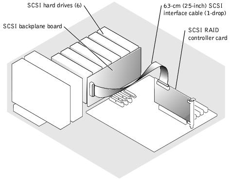
Up to six hot-plug SCSI hard drives (See Figure 7-12 and Figure 7-13.) | 38-cm (15-inch) or 63-cm (25-inch) 68-pin SCSI 1-drop cable (unterminated) | 38-cm (15-inch) cable to SCSI backplane and SCSI connector on system board (See Figure 7-12.)
or
63-cm (25-inch) cable to SCSI backplane and RAID controller card (See Figure 7-13.) |
SCSI tape drive (See Figure 7-5 and Figure 7-6.) | 68-pin SCSI 1-drop cable (terminated) | SCSI tape drive and SCSI controller on system board (See Figure 7-5.)
or
SCSI tape drive and SCSI controller card if SCSI controller is used for SCSI hard drives (See Figure 7-6.) |
NOTE: For the full name of an abbreviation or acronym used in this table, see "Abbreviations and
Acronyms."
|
The 3.5-inch diskette drive, 5.25-inch devices, and non-hot-plug hard drives must connect to a DC power cable from the system power supply. (Hot-plug SCSI drives obtain their power from the optional SCSI backplane.)
The IDE subsystem provides two channels (primary and secondary). Each channel can support up to two IDE drives such as high-capacity hard drives, CD drives, DVD drives, and tape drives.
Each IDE drive should be configured for the Cable Select setting, which assigns master and slave status to a drive according to its position on the interface cable. In this configuration, the drive attached to the last connector on the interface cable is the master or boot drive (drive 0) and the drive attached to the middle connector on the interface cable is the slave drive (drive 1). See the drive's documentation for instructions on configuring the Cable Select setting.
Table 7-2 lists guidelines for installing IDE drives connected to the IDE system board connectors.
Table 7-2. IDE Drive Configuration Guidelines
|
IDE Channel
|
System Board Connector
|
Drive Type(s)
|
|---|
1 | PRIMARY IDE | IDE hard drives |
2 | SECONDARY IDE | IDE CD, DVD, tape, or combination drives |
NOTE: The configurations shown in this table describe IDE drives connected directly to the IDE
system board connectors. To identify system board connectors, see Figure A-3.
|
Although SCSI drives are installed in essentially the same way as other drives, their configuration requirements are different. To install and configure a SCSI drive, follow the guidelines in the following subsections.
SCSI interface connectors are keyed for correct insertion. Keying ensures that the pin-1 wire in the cable connects to pin 1 in the connectors on both ends. When you disconnect an interface cable, take care to grasp the cable connector, rather than the cable itself, to avoid stress on the cable.
Each drive attached to a SCSI controller must have a unique SCSI ID number from 0 to 15.
- The SCSI hard drive from which the system boots is configured as SCSI ID 0.
- A SCSI tape drive is typically configured as SCSI ID 6.
- If you install optional SCSI drives or change your SCSI configuration, see the documentation for each SCSI drive for information on setting the appropriate SCSI ID number.
 |
NOTE: There is no requirement that SCSI ID numbers be assigned sequentially or that
drives be attached to the cable in order by ID number.
|
SCSI logic requires that termination be enabled for the two drives at opposite ends of the SCSI chain and disabled for all drives in between. For internal SCSI drives, termination is configured automatically. See the documentation provided with any optional SCSI drive you purchase for information on disabling termination.
The drive or device from which the system boots is determined by the boot order specified in the System Setup program (see "Using the System Setup Program" in your User's Guide). To boot the system from a hard drive or drive array, the drive(s) must be connected to the appropriate controller:
- To boot from a single IDE hard drive, the master drive (drive 0) must be connected to the secondary controller on the system board. To identify system board connectors, see Figure A-3.
- To boot from a single SCSI hard drive, the drive must be connected to the SCSI controller card (see the documentation that accompanied the controller card).
- To boot from an IDE or SCSI RAID array, the drive must be connected to the RAID controller card (see the documentation that accompanied the controller card).

|
CAUTION: See "Protecting Against Electrostatic Discharge" in the safety instructions in your System Information Guide. |
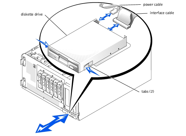
- Turn off the system, including any attached peripherals, and disconnect the system
from the electrical outlet.
- Remove the bezel (see "Removing the Bezel" in "Troubleshooting Your System").
- Remove the cover (see "Removing the Cover" in "Troubleshooting Your System").
- Lay the system on its right side.
- Use your thumb and index finger to depress the tabs that secure the diskette drive in
the drive bay (see Figure 7-1).
- Slide the diskette drive forward out of the drive bay.
- Disconnect the power cable and the interface cable from the diskette drive.
Figure 7-1. Removing a Diskette Drive
|
|
CAUTION: See "Protecting Against Electrostatic Discharge" in the safety instructions in your System Information Guide. |
- Connect the power cable and the interface cable to the diskette drive.
- Slide the diskette drive into the externally accessible drive bay (see Figure 7-1).
- Stand the system upright.
- Install the cover (see "Installing the Cover" in "Troubleshooting Your System").
- Install the bezel (see "Installing the Bezel" in "Troubleshooting Your System").
- Reconnect the system to its electrical outlet and turn the system on, including any
attached peripherals.
To help keep dust and dirt out of the system, a plastic insert in the bezel covers each empty external drive bay. Additionally, each empty external drive bay is covered by a metal insert in the chassis to maintain to maintain Federal Communications Commission (FCC) certification of the system.
Before you install a 5.25-inch drive in an empty external drive bay, you must first remove both drive inserts. If you remove a 5.25-inch drive permanently, you must install both the chassis and bezel inserts.
- Turn off the system, including any attached peripherals, and disconnect the system
from the electrical outlet.
- Remove the bezel (see "Removing the Bezel" in "Troubleshooting Your System").
- Remove the cover (see "Removing the Cover" in "Troubleshooting Your System").
- Remove the bezel drive insert:
- From inside the bezel, press the tabs at each end of the insert inward with your
thumbs.
- Pull the insert out of the bezel.
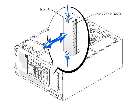
- Remove the chassis drive insert (see Figure 7-2):
- Press the tabs at each end of the insert inward.
- Pull the insert out of the chassis.
Figure 7-2. Removing the Chassis Drive Insert
 |
NOTICE: You must install both inserts in an empty 5.25-inch drive bay to maintain Federal
Communications Commission (FCC) certification of the system. The inserts also help keep dust
and dirt out of the system.
|
- Install the chassis drive insert by sliding the insert into the chassis until the tabs on the
side of the insert snap into place (see Figure 7-2).
- Install the bezel drive insert by sliding the insert into the bezel until the tabs on the
side of the insert snap into place.
- Install the cover (see "Installing the Cover" in "Troubleshooting Your System").
- Install the bezel (see "Installing the Bezel" in "Troubleshooting Your System").
- Reconnect the system to its electrical outlet and turn the system on, including any
attached peripherals.
A CD drive, DVD drive, or combination drive is standard in the first external drive bay, and an additional drive of your choice can be installed in the second external drive bay. These drives connect either to the system board or to an optional controller card.
|
|
CAUTION: See "Protecting Against Electrostatic Discharge" in the safety instructions in your System Information Guide. |
- Unpack the drive (and controller card, if applicable), and prepare the drive for
installation.
For instructions, see the documentation that accompanied the drive. Also, see "IDE Configuration Information" or "SCSI Configuration Information" for information on configuring the drive.
- Turn off the system, including any attached peripherals, and disconnect the system
from the electrical outlet.
- Remove the front-panel inserts for the empty external drive bay (see "Removing the
Front-Panel Drive Inserts").
- Lay the system on its right side.
- If the drive was supplied with a controller card, install the controller card in an
expansion slot (see "Installing an Expansion Card" in "Installing System Options").
- Slide the drive into the external drive bay.
- Install the screws that secure the drive in the drive bay (see Figure 7-3).
Figure 7-3. Installing a 5.25-Inch Drive
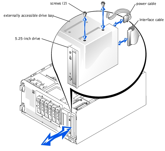
- Connect a DC power cable connector to the drive's power input connector (see
Figure 7-3).
- Connect the interface cable to the drive (see Figure 7-3) and to the system board or
controller card:
- Figure 7-4 illustrates a common cable configuration for externally accessible IDE drives.
- Figure 7-5 illustrates a SCSI tape drive connected to the SCSI controller on the system board.
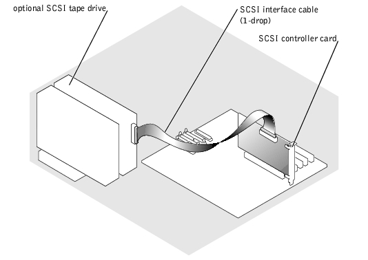
- Figure 7-6 shows a SCSI tape drive connected to a SCSI controller card.
If necessary, temporarily remove the baffle to allow easier routing of the interface cable (see "Removing the Baffle" in "Troubleshooting Your System").
For information about the controller card, see the documentation that accompanied the card.
Figure 7-4. Connecting an IDE CD Drive and Optional IDE Tape Drive to the Integrated IDE Controller
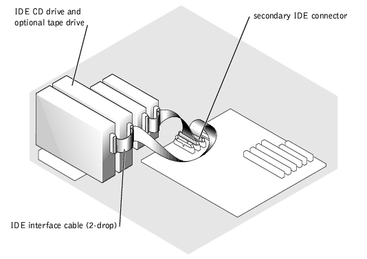
Figure 7-5. Connecting an SCSI Tape Drive to the Integrated SCSI Controller
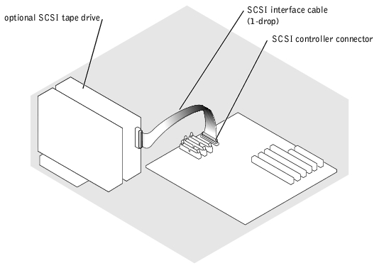
Figure 7-6. Connecting an SCSI Tape Drive to a SCSI Controller Card
- Ensure that all cables are firmly connected and arranged so that they will not catch on
the computer covers or block airflow inside the system.
- If you removed the baffle in step 9, replace the baffle now (see "Installing the Baffle" in
"Troubleshooting Your System").
- Stand the system upright.
- Install the cover (see "Installing the Cover" in "Troubleshooting Your System").
- Reconnect the system to its electrical outlet and turn the system on, including any
attached peripherals.
- Test the drive:
- If you installed an IDE drive, run the IDE devices tests in the system diagnostics to determine whether the tape drive operates properly (see "Running the System Diagnostics").
- If you installed a SCSI drive, run the SCSI controllers test in the system diagnostics (see "Running the System Diagnostics").
- If you installed a tape drive, see the tape drive software documentation to perform a backup and verification test.
You can install up to four non-hot-plug IDE or SCSI hard drives in a removable drive bay or up to six hot-plug SCSI hard drives connected to the optional SCSI backplane.
Use the following guidelines when installing hard drives:
- You should only use drives tested and approved for use in your system.
- You may need to use different programs than those provided with the operating system to partition and format a hard drive. See the hard drive's documentation for information on setting up the drive.
- When you format a high-capacity hard drive, allow enough time for the formatting to be completed. Long format times for these drives are normal. For example, a large drive can take over an hour to format.
- Do not turn off or reboot your system while the drive is being formatted. Doing so can cause a drive failure.
The SCSI controller on the system board supports integrated mirroring (RAID 1) of two SCSI drives. Both hot-plug and non-hot-plug drives can be mirrored.
Follow these guidelines to implement integrated mirroring on your system:
- If you have more than two SCSI hard drives connected to the SCSI controller on the system board, only two drives will be mirrored. Any remaining drives connected to the controller will function as conventional SCSI drives without data redundancy.
- Connect the drives to the SCSI controller as described in "Installing and Removing Hot-Plug SCSI Hard Drives" or "Installing and Removing Non-Hot-Plug Hard Drives".
- After installing the drives, use your system's array management software to configure the drives. See the array management software documentation for instructions on creating virtual disks on the mirrored drives.
|
NOTE: Dell strongly recommends that you use Dell OpenManage™ Array Manager to
enable and configure integrated mirroring.
|
For more information on this feature, see the integrated mirroring documentation provided with your system.
|
|
CAUTION: See "Protecting Against Electrostatic Discharge" in the safety instructions in your System Information Guide. |
- Turn off the system, including any attached peripherals, and disconnect the system
from the electrical outlet.
- Remove the cover (see "Removing the Cover" in "Troubleshooting Your System").
- Lay the system on its right side.
- Disconnect all power cables and interface cables from the hard drives in the drive bay.
- Remove the hard-drive bay (see Figure 7-7):
- Loosen the four Phillips-head screws that secure the drive bay in the system.
- Slide the drive bay out of the system.
- If you are removing a drive, remove the drive from the drive bay (see Figure 7-7):
- Remove the two screws that secure the drive in the drive bay.
- Slide the drive out of the drive bay.
Figure 7-7. Removing and Installing a Non-Hot-Plug Hard Drive
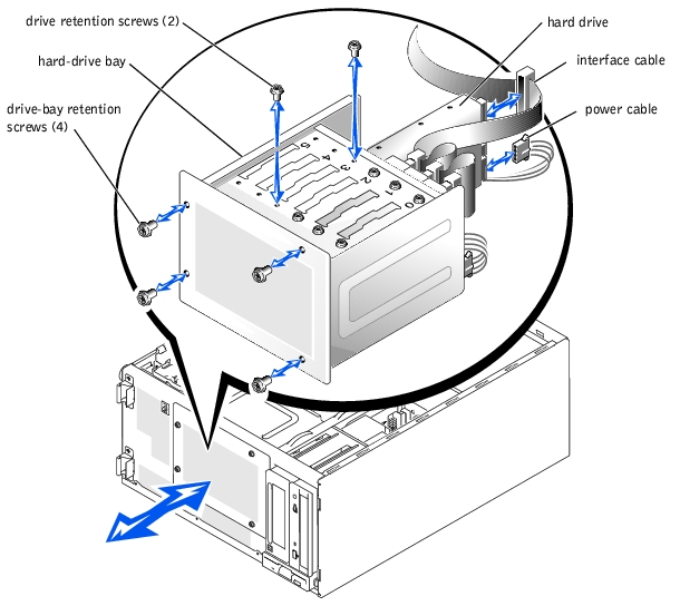
- Install the hard-drive bay (see Figure 7-7):
- With the side of the drive bay labeled "Top" facing toward the external drive bays,
slide the drive bay into the system.
- Replace the four screws that secure the drive bay in the system.
- Connect all power cables and interface cables to the hard drives remaining in the
drive bay.
- Stand the system upright.
- Install the cover (see "Installing the Cover" in "Troubleshooting Your System").
- Reconnect the system to its electrical outlet and turn the system on, including any
attached peripherals.
|
|
CAUTION: See "Protecting Against Electrostatic Discharge" in the safety instructions in your System Information Guide. |
- Unpack the drive (and controller card, if applicable), and prepare the drive for
installation.
For instructions, see the documentation that accompanied the drive. Also, see "IDE Configuration Information" or "SCSI Configuration Information" for information on configuring the drive.
- Turn off the system, including any attached peripherals, and disconnect the system
from the electrical outlet.
- Remove the cover (see "Removing the Cover" in "Troubleshooting Your System").
- Lay the system on its right side.
- If the drive was supplied with a controller card, install the controller card in an
expansion slot (see "Installing an Expansion Card" in "Installing System Options").
- Disconnect all power cables and interface cables from the hard drives in the drive bay.
- Remove the hard-drive bay (see Figure 7-7):
- Loosen the four Phillips-head screws that secure the drive bay in the system.
- Slide the drive bay out of the system.
- Install the drive in the drive bay (see Figure 7-7):
- Slide the drive into the drive bay with the back of the drive toward the back of the
drive bay.
- Install the two screws that secure the drive in the drive bay.
- Install the hard-drive bay (see Figure 7-7):
- With the side of the drive bay labeled "Top" facing toward the external drive bays,
slide the drive bay into the system.
- Replace the four screws that secure the drive bay in the system.
- Connect a DC power cable connector to the drive's power input connector.
- Connect the interface cable connector to the drive's interface connector:
- If you are installing one or two IDE hard drives, connect the interface cable between the drive(s) and the system board (see Figure 7-8).
- If you are installing one or more SCSI hard drives, connect the interface cable to the drive(s) and the SCSI controller on the system board (see Figure 7-9).
- If you are installing drives in an IDE or SCSI RAID array, connect the interface cable to the drives and the optional RAID controller card (see Figure 7-10 or Figure 7-11).
If necessary, temporarily remove the baffle to allow easier routing of the interface cable (see "Removing the Baffle" in "Troubleshooting Your System").
For information about the controller card, see the documentation that accompanied the card.
Figure 7-8. Connecting IDE Hard Drives to the Integrated IDE Controller
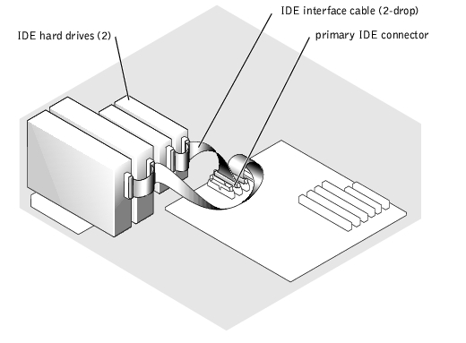
Figure 7-9. Connecting Non-Hot-Plug SCSI Hard Drives to the Integrated SCSI Controller
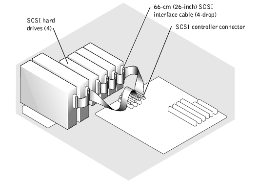
Figure 7-10. Connecting Non-Hot-Plug SCSI Hard Drives to an Optional SCSI RAID Controller Card
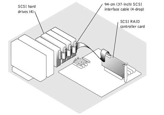
Figure 7-11. Connecting IDE Hard Drives to an Optional IDE RAID Controller Card

- Connect all power cables and interface cables to the other hard drives in the drive bay.
- Ensure that all cables are firmly connected and arranged so that they will not catch on
the computer covers or block airflow inside the system.
- If you removed the baffle in step 11, replace the baffle now (see "Installing the Baffle"
in "Troubleshooting Your System").
- Stand the system upright.
- Install the cover (see "Installing the Cover" in "Troubleshooting Your System").
- Reconnect the system to its electrical outlet and turn the system on, including any
attached peripherals.
|
NOTICE: Do not turn off or reboot your system while the drive is being formatted. Doing so
can cause a drive failure.
|
- Partition and logically format the hard drive (see the operating system
documentation).
- Test the drive:
- If you installed one or more IDE hard drives connected to the IDE controller on the system board, run the hard drive tests in the system diagnostics to determine whether the drive operates properly (see "Running the System Diagnostics").
- If you installed a drive in an IDE RAID array, run the hard drive tests in the system diagnostics (see "Running the System Diagnostics"). Also, see the RAID controller's documentation for information on testing the controller.
- If you installed one or more SCSI hard drives connected to the SCSI controller on the system board, run the SCSI controllers tests and the hard drive tests in the system diagnostics (see "Running the System Diagnostics").
- If you installed a drive in a SCSI RAID array, run the SCSI controllers tests and the hard drive tests in the system diagnostics (see "Running the System Diagnostics"). Also, see the RAID controller's documentation for information on testing the array.
The drive bays in a system with an optional SCSI backplane board provide space for up to six 1-inch hard drives. The hard drives plug into the SCSI backplane board, which is connected to a controller on the system board (see Figure 7-12) or to a RAID controller card (see Figure 7-13).
Figure 7-12. Hot-Plug SCSI Hard Drives Connected to the Integrated SCSI Controller
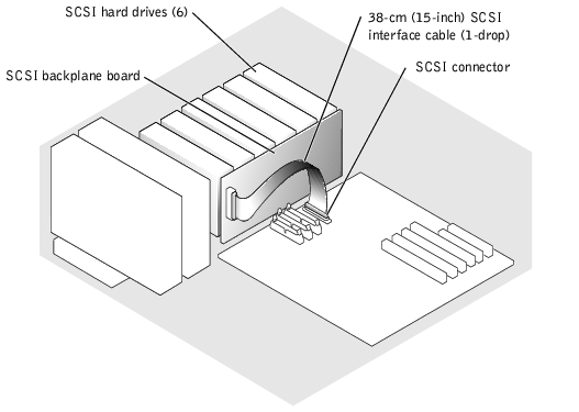
Figure 7-13. Hot-Plug SCSI Hard Drives Connected to a RAID Controller Card
|
NOTICE: Not all operating systems support hot-plug drive installation. See the documentation
supplied with your operating system.
|
- Remove the bezel (see "Removing the Bezel" in "Troubleshooting Your System").
- Take the hard drive offline and wait until the hard-drive indicator codes on the drive
carrier signal that the drive can be removed safely (see Table 2-5).
If the drive has been online, the drive-status indicator will blink green two times a second as the drive is powered down. When all indicators are off, the drive is ready for removal.
See your operating system documentation for more information on taking the hard drive offline.
- Open the hard-drive carrier handle to release the drive (see Figure 7-14).
Figure 7-14. Removing and Installing a Hot-Plug Hard-Drive
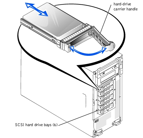
- Slide the hard drive out until it is free of the drive bay (see Figure 7-14).
- Replace the bezel (see "Installing the Bezel" in "Troubleshooting Your System").
|
NOTICE: Not all operating systems support hot-plug drive installation. See the documentation
supplied with your operating system.
|
- Remove the bezel (see "Removing the Bezel" in "Troubleshooting Your System").
- Open the hard-drive carrier handle (see Figure 7-14).
|
NOTICE: Do not insert a hard-drive carrier and attempt to lock its handle next to a partially
installed carrier. Doing so can damage the partially installed carrier's shield spring and make it
unusable. Ensure that the adjacent drive carrier is fully installed.
|
- Insert the hard-drive carrier into the drive bay (see Figure 7-14).
- Close the hard-drive carrier handle to lock it in place.
- Replace the bezel (see "Installing the Bezel" in "Troubleshooting Your System").
- Install any required SCSI device drivers.
- If the hard drive is new, run the SCSI controllers test in the system diagnostics.
Follow this general procedure when installing a RAID controller card. For specific instructions, see the documentation supplied with the card.
|
|
CAUTION: See "Protecting Against Electrostatic Discharge" in the safety instructions in your System Information Guide. |
- Unpack the expansion card, and prepare it for installation.
For instructions, see the documentation that accompanied the card.
- Turn off the system, including any attached peripherals, and disconnect the system
from the electrical outlet.
- Remove the cover (see "Removing the Cover" in "Troubleshooting Your System").
- Lay the system on its right side.
- Install the controller card in expansion slot 1 or 2 (see "Installing an Expansion Card"
in "Installing System Options").
- Connect the interface cable to the card and to the drives.
See Figure 7-10, Figure 7-12, and the documentation that accompanied the card for information about cable connections between the drives and RAID card.
- Stand the system upright.
- Install the cover (see "Installing the Cover" in "Troubleshooting Your System").
- Reconnect the system to its electrical outlet and turn the system on, including any
attached peripherals.
- Ensure that any required device drivers are installed and are configured correctly.
For information on installing device drivers, see the Dell OpenManage Server Assistant CD and the documentation that accompanied the controller card.
- Test the array:
Also, see the RAID controller's documentation for information on testing the array.
Back to Contents Page