Back to Contents Page
Dell™ PowerEdge™ 1600SC Systems
Installation and Troubleshooting Guide
 System Fans
Redundant Power Supplies
Expansion Cards
Memory Modules
Microprocessors
System Battery
This section describes how to remove and install the following components:
- System fans
- Optional redundant power supplies
- Expansion cards
- Memory modules
- Microprocessors
- System battery
For information on installing a hard drive or other drives, see "Installing Drives."
Your system includes the following system cooling fans:
- Front system fan
- Back system fan

|
CAUTION: See "Protecting Against Electrostatic Discharge" in the safety instructions in your System Information Guide. |
- Turn off the system, including any attached peripherals, and disconnect the system
from the electrical outlet.
- Remove the bezel (see "Removing the Bezel" in "Troubleshooting Your System").
- Remove the cover (see "Removing the Cover" in "Troubleshooting Your System").
- Lay the system on its right side.
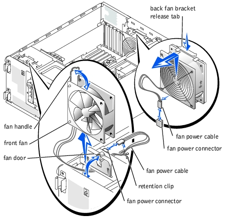
- Disconnect the fan power cable from the fan power connector on the chassis (see
Figure 6-1).
- Remove the fan power cable from the plastic retention clip.
- Open the fan door (see Figure 6-1).
- Pull the wire handle on the fan upward and slide the fan out of the system (see
Figure 6-1).
Figure 6-1. Removing the Front and Back System Fans
|
|
CAUTION: See "Protecting Against Electrostatic Discharge" in the safety instructions in your System Information Guide. |
- Insert the fan power cable into the fan bay and connect the fan power cable to the fan
power connector on the chassis (see Figure 6-1).
- Slide the fan into the system chassis (see Figure 6-1), being careful not to trap the
power cable between the fan and chassis.
- Secure the fan power cable with the plastic retention clip (see Figure 6-1).
- Close the fan handle.
- Close the fan door.
- Stand the system upright.
- Install the cover (see "Installing the Cover" in "Troubleshooting Your System").
- Install the bezel (see "Installing the Bezel" in "Troubleshooting Your System").
- Reconnect the system to its electrical outlet and turn the system on, including any
attached peripherals.
|
|
CAUTION: See "Protecting Against Electrostatic Discharge" in the safety instructions in your System Information Guide. |
- Turn off the system, including any attached peripherals, and disconnect the system
from the electrical outlet.
- Remove the cover (see "Removing the Cover" in "Troubleshooting Your System").
- Lay the system on its right side.
- Disconnect the fan power cable from the fan power connector on the system board.
To identify system board connectors, see Figure A-3.
- Pull the fan bracket release tab away from the back panel and slide the fan assembly
upward about 1 cm (0.5 inch) (see Figure 6-1).
- Lift the fan assembly away from the back panel and out of the system.
|
|
CAUTION: See "Protecting Against Electrostatic Discharge" in the safety instructions in your System Information Guide. |
- Insert the four tabs on the fan bracket into the mounting holes in the back panel and
slide the fan assembly downward about 1 cm (0.5 inch) until the fan bracket release
tab snaps into place.
- Connect the fan power cable to the fan power connector on the system board.
To identify system board connectors, see Figure A-3.
- Stand the system upright.
- Install the cover (see "Installing the Cover" in "Troubleshooting Your System").
- Reconnect the system to its electrical outlet and turn the system on, including any
attached peripherals.
The optional redundant power supplies are accessible from the back panel.
|
|
CAUTION: To prevent risk of personal injury from electrical shock, do not reach into an empty power supply bay. |
 |
NOTICE: The power supplies are hot-pluggable. The system requires one power supply to be
installed for the system to operate normally. The system is in the redundant mode when two
power supplies are installed. Remove and replace only one power supply at a time in a system
that is powered on.
|
- Disconnect the power cord from the power supply.
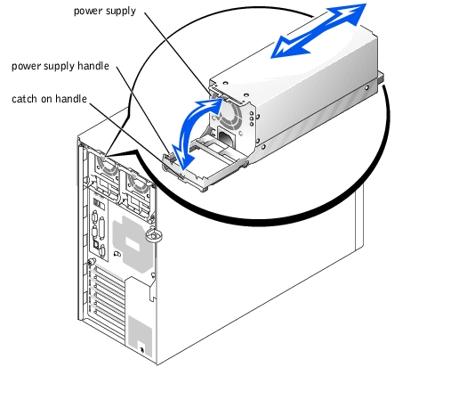
- Using your thumb and index finger, squeeze the catch in the middle of the power
supply handle (see Figure 6-2).
- Rotate the handle downward to release the power supply.
- Slide the power supply out of the chassis.
- Slide the power supply into the chassis.
- When the power supply is fully inserted, rotate the power supply handle upward to
lock the power supply in place.
The power supply will not function until the handle is fully closed.
- Plug the power cable into the power supply, making sure that the cable passes through
the power cable strain relief loop.
 |
NOTE: After installing a new power supply, allow several seconds for the system to
recognize the power supply and determine whether it is working properly. The
power-on indicator turns green to signify that the power supply is functioning properly
(see Figure 2-3).
|
Figure 6-2. Removing and Installing an Optional Redundant Power Supply
The system includes six expansion slots, configured as follows:
- Slots 1 and 2 are 64-bit, 66-MHz PCI slots (3.3 V).
- Slots 3 and 4 are 64-bit, 100-MHz PCI-X slots (3.3 V).
- Slots 5 and 6 are 32-bit, 33-MHz PCI slots (5 V).
All expansion slots accommodate full-length cards, except for slot 1.
To identify expansion slots and operating speeds, see Figure A-3.
|
|
CAUTION: See "Protecting Against Electrostatic Discharge" in the safety instructions in your System Information Guide. |
|
NOTE: If you install a RAID controller card, install the card in expansion slot 1 or 2.
(See Figure A-3 to locate these expansion slots.)
|
- Unpack the expansion card, and prepare it for installation.
For instructions, see the documentation that accompanied the card.
- Turn off the system, including any attached peripherals, and disconnect the system
from the electrical outlet.
- Remove the cover (see "Removing the Cover" in "Troubleshooting Your System").
- Lay the system on its right side.
- Remove the filler bracket from the expansion slot.
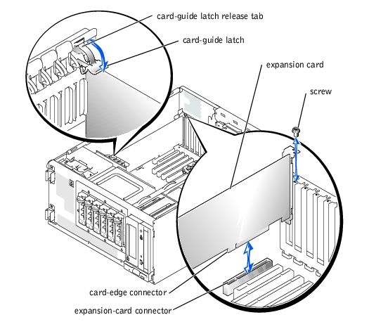
- Install the expansion card (see Figure 6-3):
- Position the expansion card so that the card-edge connector aligns with the
expansion-card connector on the system board.
- Insert the card-edge connector firmly into the expansion-card connector until the
card is fully seated.
- Install the screw that secures the expansion-card bracket to the back panel.
- If the card is a full-length card, close the card-guide latch.
- Connect any cables that should be attached to the card.
See the documentation that accompanied the card for information about its cable connections.
- Stand the system upright.
- Install the cover (see "Installing the Cover" in "Troubleshooting Your System").
- Reconnect the system to its electrical outlet and turn the system on, including any
attached peripherals.
Figure 6-3. Removing and Installing an Expansion Card
|
|
CAUTION: See "Protecting Against Electrostatic Discharge" in the safety instructions in your System Information Guide. |
- Turn off the system, including any attached peripherals, and disconnect the system
from the electrical outlet.
- Remove the cover (see "Removing the Cover" in "Troubleshooting Your System").
- Lay the system on its right side.
- Disconnect any cables attached to the card.
- Remove the expansion card (see Figure 6-3):
- If the card is a full-length card, press the release tab on the card-guide latch and
open the latch.
- Remove the screw that secures the expansion-card bracket to the back panel.
- Grasp the expansion card by its top corners, and carefully remove it from the
expansion-card connector.
- If you are removing the card permanently, install a metal filler bracket over the empty
expansion slot opening and close the expansion-card latch.
|
NOTICE: You must install a filler bracket over an empty expansion slot to maintain Federal
Communications Commission (FCC) certification of the system. The brackets also help keep dust
and dirt out of the system and aid in proper cooling and airflow inside the system.
|
- Stand the system upright.
- Install the cover (see "Installing the Cover" in "Troubleshooting Your System").
- Reconnect the system to its electrical outlet and turn the system on, including any
attached peripherals.
The four memory module connectors on the system board can accommodate from 128 MB to 4 GB of registered memory modules.
System memory is upgradable to 4 GB by installing combinations of 128-, 256-, 512-MB, and 1-GB registered DDR SDRAM modules. You can purchase memory upgrade kits as needed.
|
NOTICE: The DDR SDRAM memory modules must be PC-266 compliant.
|
Starting with the connector nearest the side of the system board, the memory module sockets are labeled "DIMMA" through "DIMMD" (see Figure A-3). When you install memory modules, install the first module in connector DIMMA before installing additional modules in connectors DIMMB, DIMMC, and DIMMD.
Table 6-1 lists sample memory configurations based on these guidelines.
Table 6-1. Sample Memory Module Configurations
|
Total Memory
|
DIMMA
|
DIMMB
|
DIMMC
|
DIMMD
|
|---|
128 MB | 128 MB | None | None | None |
512 MB | 256 MB | 256 MB | None | None |
512 MB | 512 MB | None | None | None |
1 GB | 512 MB | 512 MB | None | None |
1.5 GB | 1 GB | 512 MB | None | None |
2 GB | 512 MB | 512 MB | 512 MB | 512 MB |
3 GB | 1 GB | 1 GB | 1 GB | None |
3 GB | 1 GB | 1 GB | 512 MB | 512 MB |
4 GB | 1 GB | 1 GB | 1 GB | 1 GB |
NOTE: This table only lists sample memory module configurations. Not all
possible configurations are listed.
|
|
|
CAUTION: See "Protecting Against Electrostatic Discharge" in the safety instructions in your System Information Guide. |
- Turn off the system, including any attached peripherals, and disconnect the system
from the electrical outlet.
- Remove the cover (see "Removing the Cover" in "Troubleshooting Your System").
- Lay the system on its right side.
- Install or remove memory modules as necessary to reach the desired memory total (see
"Installing Memory Modules" and "Removing Memory Modules").
See Figure A-3 to locate the memory module connectors.
- Stand the system upright.
- Install the cover (see "Installing the Cover" in "Troubleshooting Your System").
- Reconnect the system to its electrical outlet and turn the system on, including any
attached peripherals.
After the system completes the POST routine, it runs a memory test.
The system detects that the new memory does not match the system configuration information, which is stored in NVRAM. The monitor displays an error message that ends with the following words:
Press <F1> to continue; <F2> to enter System Setup
- Press <F2> to enter the System Setup program, and check the System Memory
setting.
The system should have already changed the value in the System Memory setting to reflect the newly installed memory.
- If the System Memory value is incorrect, one or more of the memory modules may not
be installed properly. Repeat step 1 through step 8, ensuring that the memory modules
are firmly seated in their connectors.
- Run the system memory test in the system diagnostics.
|
|
CAUTION: See "Protecting Against Electrostatic Discharge" in the safety instructions in your System Information Guide. |
- Turn off the system, including any attached peripherals, and disconnect the system
from the electrical outlet.
- Remove the cover (see "Removing the Cover" in "Troubleshooting Your System").
- Lay the system on its right side.
- Locate the memory module connectors in which you will install a memory module
(see Figure A-3).
- Press down and outward on the memory module connector ejectors, as shown in
Figure 6-4, to allow the memory module to be inserted into the connector.
Figure 6-4. Removing and Installing a Memory Module
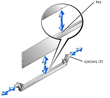
- Align the notch in the memory module's edge connector with the alignment key in the
socket, and insert the memory module in the connector (see Figure 6-4).
The memory module connector has an alignment key that allows the memory module to be installed in the connector in only one way.
- Press down on the memory module with your thumbs while pulling up on the ejectors
with your index fingers to lock the memory module into the connector (see
Figure 6-4).
When the memory module is properly seated in the connector, the memory module connector ejectors should align with the ejectors on the other connectors with memory modules installed.
- Repeat step 4 through step 7 to install the remaining memory modules.
- Perform step 5 through step 10 of "Performing a Memory Upgrade."
|
|
CAUTION: See "Protecting Against Electrostatic Discharge" in the safety instructions in your System Information Guide. |
- Turn off the system, including any attached peripherals, and disconnect the system
from the electrical outlet.
- Remove the cover (see "Removing the Cover" in "Troubleshooting Your System").
- Lay the system on its right side.
- Locate the memory module connectors from which you will remove memory modules
(see Figure A-3).
- Press down and outward on the memory module connector ejectors until the memory
module pops out of the connector (see Figure 6-4).
- Repeat step 4 and step 5 of this procedure to remove any other memory modules.
- Perform step 5 through step 10 of "Performing a Memory Upgrade."
To take advantage of future options in speed and functionality, you can add a second microprocessor or replace either the primary or secondary microprocessor.
|
NOTE: The second microprocessor must be of the same type as the first. If the two
microprocessors are different speeds, both will operate at the speed of the slower
microprocessor.
|
Each microprocessor and its associated cache memory are contained in a PGA package that is installed in a ZIF socket on the system board.
The following items are included in the microprocessor upgrade kit:
- A microprocessor
- A heat sink with cooling fan
|
|
CAUTION: See "Protecting Against Electrostatic Discharge" in the safety instructions in your System Information Guide. |
- Turn off the system, including any attached peripherals, and disconnect the system
from the electrical outlet.
- Remove the cover (see "Removing the Cover" in "Troubleshooting Your System").
- Lay the system on its right side.
- If you are removing or installing a microprocessor in socket CPU2, remove the vertical
plastic baffle to improve access to the microprocessor socket (see "Removing the
Baffle" in "Troubleshooting Your System").
- Disconnect the microprocessor fan cable from the fan power connector on the system
board (see Figure 6-5).
To identify system board connectors, see Figure A-3.
- Remove the back system fan (see "Removing the Back System Fan").
|
|
CAUTION: The microprocessor and heat sink can become extremely hot. Be sure they have had sufficient time to cool before handling. |
|
NOTICE: Do not operate the system without the fan and heat sink assembly installed. The
assembly is required to maintain proper thermal conditions.
|
|
NOTICE: After removing the fan and heat sink assembly, place it upside down on a flat surface
to prevent the thermal interface material on the heat sink from being damaged or contaminated.
|
|
NOTICE: The microprocessor fan and heat sink are constructed together as a single assembly.
Do not attempt to remove the fan from the heat sink.
|
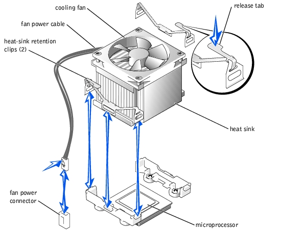
- Remove the microprocessor fan and heat sink assembly (see Figure 6-5):
- Press down on the release tabs on the heat-sink retention clips to release the clips
from the retaining tabs on the ZIF socket.
- Lift the assembly away from the microprocessor.
Figure 6-5. Removing the Microprocessor Fan and Heat Sink Assembly
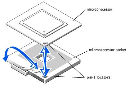
- Pull the microprocessor socket release lever upward to the fully open position (see
Figure 6-6).
|
NOTICE: Be careful not to bend any of the pins when removing the microprocessor. Bending
the pins can permanently damage the microprocessor.
|
- Lift the microprocessor out of the socket and leave the release lever in the open
position so that the socket is ready for the new microprocessor (see Figure 6-6).
Figure 6-6. Removing and Installing a Microprocessor
- Unpack the new microprocessor.
If any of the pins on the microprocessor appear bent, see "Getting Help" for instructions on obtaining technical assistance.
- Ensure that the microprocessor socket release lever is in the fully open position.
|
NOTICE: The microprocessor and system board can be damaged if the microprocessor socket
release lever is not fully open when you insert the new microprocessor.
|
- Align pin 1 on the microprocessor (see Figure 6-6) with pin 1 on the microprocessor
socket.
|
NOTICE: Positioning the microprocessor incorrectly can permanently damage the
microprocessor and the system when you turn on the system. When placing the microprocessor
in the socket, be sure that all of the pins on the microprocessor go into the corresponding holes
and that the processor is parallel to the surface of the socket. Be careful not to bend the pins.
|
- Install the microprocessor in the socket (see Figure 6-6).
|
NOTE: No force is needed to install the microprocessor in the socket. When the
microprocessor is aligned correctly, it should drop into the socket.
|
- When the microprocessor is fully seated in the socket, rotate the socket release lever
back down until it snaps into place, securing the microprocessor in the socket.
- Place the microprocessor fan and heat sink assembly on top of the microprocessor (see
Figure 6-5).
- To reinstall the heat-sink retention clips, hold the clip by the release tab (see
Figure 6-5), fit the opposite end of the clip over the tab on the microprocessor socket,
and press down on the release tab until the free end of the clip snaps into place.
|
NOTICE: The cooling fan must be connected for the microprocessor to maintain proper thermal
conditions.
|
- Connect the microprocessor fan cable to the fan connector on the system board (see
Figure 6-5).
To identify system board connectors, see Figure A-3.
- Reinstall the back system fan (see "Installing the Back System Fan").
- If you removed the baffle in step 4, replace the baffle now (see "Installing the Baffle" in
"Troubleshooting Your System").
|
NOTICE: You must reinstall the baffle to maintain proper airflow for system cooling.
|
- Stand the system upright.
- Install the cover (see "Installing the Cover" in "Troubleshooting Your System").
- Reconnect the system to its electrical outlet and turn the system on, including any
attached peripherals.
- Enter the System Setup program, and ensure that the microprocessor options match
the new system configuration (see "Using the System Setup Program" in your User's
Guide).
As the system boots, it detects the presence of the new microprocessor and automatically changes the system configuration information in the System Setup program. A message similar to the following appears:
One 1.8 GHz Processor, Processor Bus: 400 MHz, L2 cache
512 KB Advanced
- Confirm that the top line of the system data area in the System Setup program
correctly identifies the installed microprocessor(s) (see "Using the System Setup
Program" in your User's Guide).
- Exit the System Setup program.
- Run the system diagnostics to verify that the new microprocessor is operating
correctly.
See "Running the System Diagnostics" for information on running the diagnostics and troubleshooting any problems that may occur.
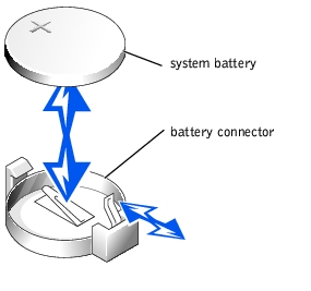
The system battery is a 3-V, coin-cell battery.
|
|
CAUTION: See "Protecting Against Electrostatic Discharge" in the safety instructions in your System Information Guide. |
|
|
CAUTION: There is a danger of a new battery exploding if it is incorrectly installed. Replace the battery only with the same or equivalent type recommended by the manufacturer. Discard used batteries according to the manufacturer's instructions. See your System Information Guide for additional information. |
- Turn off the system, including any attached peripherals, and disconnect the system
from the electrical outlet.
- Remove the cover (see "Removing the Cover" in "Troubleshooting Your System").
- Lay the system on its right side.
See Figure A-3 to locate the system battery on the system board.
- If necessary, remove the expansion cards to access the battery socket.
See "Removing an Expansion Card."
- Remove the system battery (see Figure 6-7).
You can pry the system battery out of its connector with your fingers or with a blunt, nonconductive object such as a plastic screwdriver.
- Install the new system battery with the side labeled "+" facing up (see Figure 6-7).
- If you removed expansion cards in step 4, replace them now.
See "Installing an Expansion Card."
- Stand the system upright.
- Install the cover.
See "Installing the Cover" in "Troubleshooting Your System."
- Reconnect the system to its electrical outlet and turn the system on, including any
attached peripherals.
Figure 6-7. Replacing the System Battery
- Enter the System Setup program to confirm that the battery is operating properly (see
"Using the System Setup Program" in your User's Guide).
- Enter the correct time and date in the System Setup program's Time and Date fields.
- Exit the System Setup program.
- To test the newly installed battery, turn off the system and disconnect it from the
electrical outlet for at least an hour.
- After an hour, reconnect the system to its electrical outlet and turn it on.
- Enter the System Setup program and if the time and date are still incorrect, see
"Getting Help" for instructions on obtaining technical assistance.
Back to Contents Page