 Requirements
Dell™ PowerEdge™ Expandable RAID Controller 4/SC and 4/DC User's Guide
This section describes the procedures for installing the PERC 4/SC/DC controllers. You must have the following items to install the RAID controller:
Perform the following steps for quick installation of the controller if you are an experienced computer user/installer. All others should follow the steps under the heading Installation Steps in this section.
This section provides instructions for installing the PERC 4 RAID controllers.
 |
NOTICE: See the safety instructions in your system documentation for information about protecting against electrostatic discharge. |
Unpack and remove the controller and inspect it for damage. If the controller appears damaged, or if any items listed below are missing, contact your Dell support representative. The PERC 4 controller is shipped with:
 |
NOTE: You can order a hard copy of the documentation for the controller. |
Turn off the system and remove the AC power cord. Disconnect the system from any networks before installing the controller. Remove the system's cover. Please consult the system documentation for instructions.
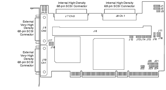
Make sure the jumper settings on the PERC 4/SC or PERC 4/DC controller are correct. Following are diagrams of the controllers showing their jumpers and connectors, and tables describing them. Select your controller from the ones shown on the following pages.
Figure 3-1. PERC 4/SC Controller Layout
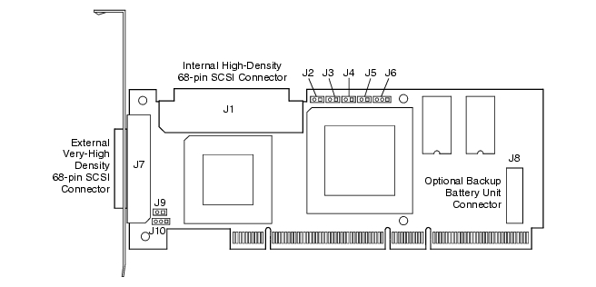
Figure 3-2. PERC 4/DC Controller Layout
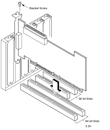
Select a 3.3V PCI slot and align the controller PCI bus connector to the slot. Press down gently but firmly to make sure that the controller is properly seated in the slot, as shown in Figure 3-3. Screw the bracket to the system chassis.
Figure 3-3. Inserting the PERC 4 Controller into a PCI Slot
Connect the SCSI cables to the SCSI connectors and SCSI devices.
Perform the following steps to connect SCSI devices.
The host controller has a SCSI ID of 7.
The maximum cable length for Fast SCSI (10 MB/s) devices or single ended (SE) is 3 meters. For Ultra SCSI devices, it is 1.5 meters. The cable length can be up to 12 meters for LVD devices.
System throughput problems can occur if SCSI cable are not the correct. You should:
Set target identifiers (TIDs) on the SCSI devices. Each device in a channel must have a unique TID. Non-disk devices should have unique SCSI IDs regardless of the channel where they are connected. See the documentation for each SCSI device to set the TIDs. The PERC 4 controller automatically occupies TID 7 which is the highest priority. The arbitration priority for a SCSI device depends on its TID. Table 3-3 lists the target IDs.
| Priority |
Highest Lowest |
|||||||||||
| TID |
7 |
6 |
5 |
... |
2 |
1 |
0 |
15 |
14 |
... |
9 |
8 |
The SCSI bus is an electrical transmission line and must be terminated properly to minimize reflections and losses. Termination should be set at each end of the SCSI cable(s).
For a disk array, set SCSI bus termination so that removing or adding a SCSI device does not disturb termination. An easy way to do this is to connect the controller to one end of the SCSI cable and to connect an external terminator module at the other end of the cable. The connectors between the two ends can connect SCSI devices. Disable termination on the SCSI devices. See the manual for each SCSI device to disable termination.
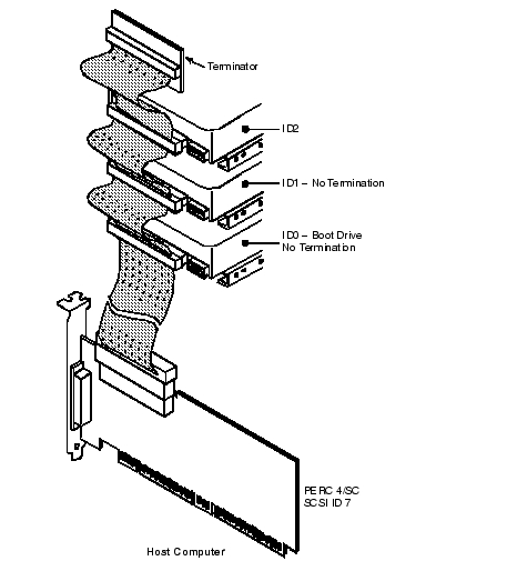
Set the termination so that SCSI termination and TermPWR are intact when any hard drive is removed from a SCSI channel, as shown in Figure 3-4.
Figure 3-4. Terminating Internal SCSI Disk Array
Replace the system cover and reconnect the AC power cords. Turn power on to the host system. Set up the power supplies so that the SCSI devices are powered up at the same time as or before the host system. If the system is powered up before a SCSI device, the device might not be recognized.
During boot, the PERC 4 BIOS message appears:
PowerEdge Expandable RAID Controller BIOS Version x.xx date
Copyright (c) Dell Computer Corporation
Firmware Initializing... [ Scanning SCSI Device ...(etc.)... ]
The firmware takes several seconds to initialize. During this time the adapter scans the SCSI channel. When ready, the following appears:
HA –0 (Bus 1 Dev 6) Type: PERC 4/xx Standard FW x.xx SDRAM=xxxMB
0 Logical Drives found on the Host Adapter
0 Logical Drive(s) handled by BIOS
Press <Ctrl><M> to run PERC 4 BIOS Configuration Utility
Or press <Ctrl><H> to run WebBIOS
The PERC 4 BIOS Configuration Utility prompt times out after several seconds.
The PERC 4 host controller number, firmware version, and cache SDRAM size display in the second portion of the BIOS message. The numbering of the controllers follows the PCI slot scanning order used by the host motherboard.
When you start the system, the boot block and firmware perform a number of steps that load the operating system and allow the computer to function properly. The boot block contains the operating system loader and other basic information needed during startup.
As the system boots, the LEDs indicate the status of the boot block and firmware initialization and whether the system performed the steps correctly. If there is an error during startup, you can use the LED display to identify it.
Table 3-4 displays the LEDs and execution states for the boot block. Table 3-5 displays the LEDs and execution states during firmware initialization. The LEDs display in hexadecimal format so that you can determine the number and the corresponding execution state from the LEDs that display.
| LED |
Execution State |
|---|---|
0x1 |
Begin Hardware Initialization |
0x3 |
Begin Initialize ATU |
0x7 |
Begin Initialize Debug Console |
0xF |
Set if Serial Loopback Test is successful |
Press <Ctrl><M> when prompted during the boot process to run the BIOS Configuration Utility or <Ctrl><H> to run the WebBIOS Configuration Utility. You can also run Dell Manager in Novell NetWare and Red Hat Linux to perform the same functions, such as configuring arrays and logical drives.
See PERC 4 BIOS Configuration Utility for additional information about running the PERC 4 BIOS Configuration Utility. WebBIOS is an HTML-based configuration utility. See WebBIOS Configuration Utility, for additional information about running the WebBIOS Configuration Utility and Dell Manager, for additional information about running Dell Manager.
Install one of the following operating systems: Microsoft® Windows NT®, Windows® 2000, Windows XP, Windows Server 2003, Novell® NetWare®, and Red Hat Linux.
Operating system drivers are provided on the Dell OpenManage Server Assistant CD that accompanies your PERC controller. See the PERC 4 RAID Controller Operating System Driver Installation Guide for additional information about installing the drivers for the operating systems.