Back to Contents Page
Dell™ PowerEdge™ 2600 Systems
Installation and
Troubleshooting Guide
 Cooling Shroud
System Fans
Power Supplies
Expansion Cards
Memory Modules
Microprocessors
System Battery
This section describes how to remove and replace the following components:
- Cooling shroud
- System fans
- Power supplies
- Expansion cards
- Memory modules
- Microprocessors
- System battery
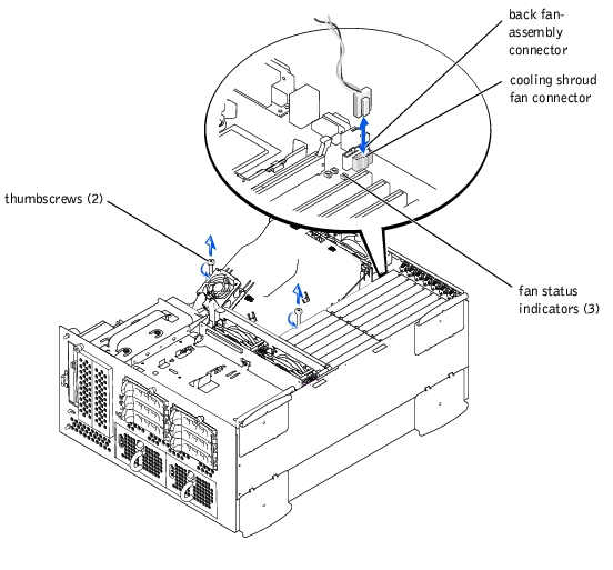
The cooling shroud is attached to the back fan assembly and secured to the system board with two thumbscrews.
- Open the bezel (see "Removing the Bezel" in "Troubleshooting Your System").
- Turn off the system, including any attached peripherals, and disconnect the system
from the electrical outlet.
- Remove the cover (see "Removing the Cover" in "Troubleshooting Your System").
- Disconnect the cooling shroud fan power cable from the fan connector on the system
board (see Figure 6-1).
- Loosen the two thumbscrews securing the cooling shroud to the system board (see
Figure 6-1).
Figure 6-1. Removing and Replacing the Cooling Shroud
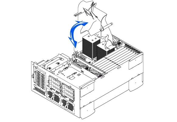
- Rotate the cooling shroud up and lift to clear the back fan assembly and chassis (see
Figure 6-2).
Figure 6-2. Rotating the Cooling Shroud
- Lower the cooling shroud into the chassis ensuring that the cooling shroud is aligned
with the rear cooling fan assembly guides.
- Rotate the cooling shroud down ensuring the thumbscrews are aligned with the
connecting posts on the system board (see Figure 6-1).
- Tighten the two thumbscrews securing the cooling shroud to the system board.
- Reconnect the cooling shroud fan cable to the system board.
- Replace the cover (see "Replacing the Cover" in "Troubleshooting Your System").
The system includes the following hot-pluggable cooling fans:
- Two fan assemblies containing two individual fans. One assembly is located near the SCSI backplane board. The other fan assembly is attached to the back of the chassis.
- One cooling fan located on the cooling shroud.

|
CAUTION: See "Protecting Against Electrostatic Discharge" in the safety
instructions in your System Information document.
|
- Open the bezel (see "Removing the Bezel" in "Troubleshooting Your System").
- Turn off the system, including any attached peripherals, and disconnect the system
from the electrical outlet.
- Remove the cover (see "Removing the Cover" in "Troubleshooting Your System").
- Disconnect the front fan assembly power cable from the front fan connector on the
SCSI backplane board (see Figure A-4).
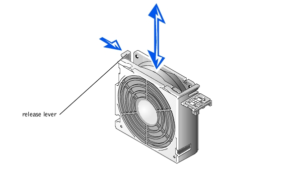
- Release the fan assembly by pressing the release lever (see Figure 6-3).
- Swing the fan assembly up and out of the way.
Figure 6-3. Removing and Replacing the Front-Fan Assembly
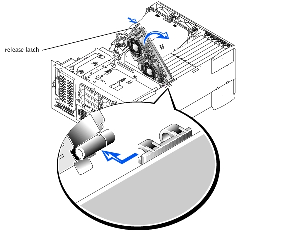
- Place the fan assembly in the hinge bracket and swing the fan assembly down until the
release lever snaps into place.
- Connect the fan assembly power cable to the front fan connector on the SCSI
backplane board (see Figure A-4).
- Replace the cover (see "Replacing the Cover" in "Troubleshooting Your System").
|
|
CAUTION: See "Protecting Against Electrostatic Discharge" in the safety
instructions in your System Information document.
|
- Open the bezel (see "Removing the Bezel" in "Troubleshooting Your System").
- Turn off the system, including any attached peripherals, and disconnect the system
from the electrical outlet.
- Remove the cover (see "Removing the Cover" in "Troubleshooting Your System").
- Remove the cooling shroud (see "Removing the Cooling Shroud").
- Disconnect the fan assembly power cable from the back fan connector on the system
board (see Figure A-3).
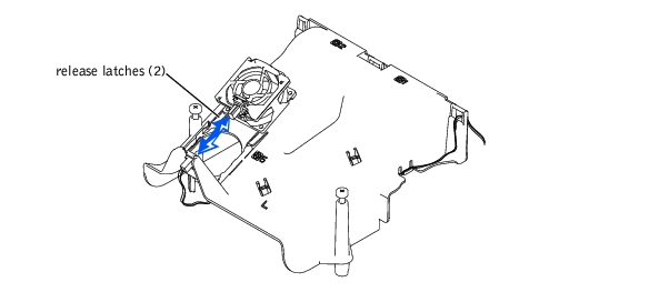
- Pull on the release latch and lift the fan assembly straight up to clear the chassis (see
Figure 6-4).
Figure 6-4. Removing and Replacing the Back Fan Assembly
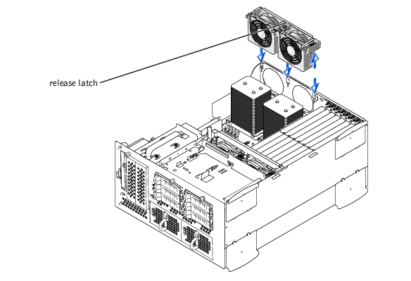
- Align the fan assembly with the fan assembly guide on the back of the chassis, and
push down until the fan assembly is firmly seated and the latch is engaged (see
Figure 6-4).
- Connect the fan assembly power cable to the back fan connector on the system board
(see Figure 6-4).
- Install the cooling shroud (see "Installing the Cooling Shroud").
- Replace the cover (see "Replacing the Cover" in "Troubleshooting Your System").
Each fan assembly contains two fans. The procedure for removing and replacing the four individual fans are the same.
- Remove the system cover (see "Removing the Cover" in "Troubleshooting Your
System").
|
|
CAUTION: The cooling fans are hot-pluggable. To maintain proper cooling while
the system is on, only replace one fan at a time.
|
- Locate the faulty fan and while pressing the fan release lever, lift the fan straight up to
clear the fan assembly (see Figure 6-5).
Figure 6-5. Removing and Replacing Individual Fans
- Lower the fan into the fan assembly until the fan snaps into position.
- Replace the cover (see "Replacing the Cover" in "Troubleshooting Your System").
- Remove the cover (see "Removing the Cover" in "Troubleshooting Your System").
- Push down on the two release latches and slide the fan out of the bracket on the
cooling shroud (see Figure 6-6).
Figure 6-6. Removing and Replacing the Cooling Shroud Fan
- Slide the fan into the bracket on the cooling shroud until the fan snaps into position
(see Figure 6-6).
- Replace the system cover.
The system includes one or two hot-pluggable power supplies.
|
|
CAUTION: The power supplies are hot-pluggable. The system requires one power
supply to be installed for the system to operate normally. The system is in the
redundant mode when two power supplies are installed. Remove and replace only
one power supply at a time in a system that is powered on.
|
- Open the bezel (see "Removing the Bezel" in "Troubleshooting Your System").
- Grasp the power-supply handle and press down on the release lever while pulling the
power supply straight out to clear the chassis (see Figure 6-7).
Figure 6-7. Removing and Replacing a Power Supply
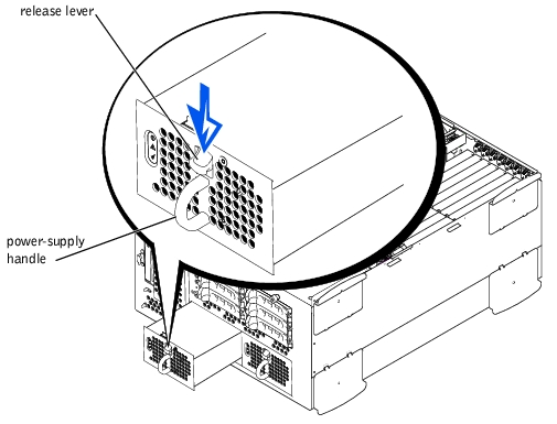
- Slide the power supply into the chassis until it snaps into place (see Figure 6-7).
 |
NOTE: After installing a new power supply, allow several seconds for the system to
recognize the power supply and determine whether it is working properly. The power-on
indicator will turn green to signify that the power supply is functioning properly (see
Figure 2-4).
|
- Close the bezel (see "Replacing the Bezel" in "Troubleshooting Your System").
The system includes seven expansion slots. The expansion cards are installed on the system board (see Figure A-3 to identify the expansion slots).
You can install expansion cards of different operating speeds on the same bus; however, the bus will operate at the slowest operating speed of the cards on that bus. For example, if one card on the bus has an operating speed of 66 MHz and the other card has an operating speed of 100 MHz, the bus will only operate at 66 MHz.
To identify expansion slots, see Figure A-3. Table 6-1 lists the PCI bus and operating speed for each expansion-card slot.
Table 6-1. Expansion Slot Speeds
|
Slot
|
Bus
|
Operating Speed
|
|---|
1 | 0 | 33 MHz |
2 | 5 | 33, 66, or 100 MHz |
3 | 5 | 33, 66, or 100 MHz |
4 | 4 | 33, 66, or 100 MHz |
5 | 4 | 33, 66, or 100 MHz |
6 | 3 | 33, 66, 100, or 133 MHz |
7 | 2 | 33, 66, 100, or 133 MHz |
NOTE: If you are using expansion cards of different operating speeds, you should install the fastest
card in slot 7 and the slowest card in slot 1.
NOTE: For the full name of an abbreviation or acronym used in this table, see "Abbreviations and
Acronyms."
|
The system's BIOS scans and numbers PCI buses and devices during startup. Expansion slots are scanned according to the host bus ordering, not by the slot numbers. See Table 6-2 for the order in which the expansion slots and embedded PCI devices are scanned.
An additional factor affects the assignment of PCI bus numbers: an expansion card may have its own PCI bridge chip which requires the assignment of a bus number for the card as well as one for the bridge. A particular expansion card may have two PCI bridge chips which would result in three sequential PCI bus numbers all assigned in the same expansion slot.
If you install expansion cards, you may have some difficulty in directly determining the bus number of a controller on a particular expansion card. However, the PCI bus scan order listed in Table 6-2 can help determine the relative numbering of PCI buses within the expansion slots. For example, a PCI controller residing in expansion slot 3 will never have a lower bus number than one in slot 2 because slot 2 precedes slot 3 in the scan order.
Table 6-2. PCI Bus Scan Order
|
Order
|
Device or Slot
|
|---|
1 | Expansion slot 1 |
2 | Embedded remote access components |
3 | Video |
4 | Integrated Gigabit NIC |
5 | Expansion slot 7 |
6 | Expansion slot 6 |
7 | Expansion slot 4 |
8 | Expansion slot 5 |
9 | Expansion slot 4 |
10 | Expansion slot 3 |
11 | Expansion slot 2 |
12 | Optional integrated RAID controller on the system board |
13 | Integrated SCSI controller on the system board |
NOTE: For the full name of an abbreviation or acronym used in this table, see "Abbreviations and
Acronyms."
|
|
|
CAUTION: Before you perform this procedure, you must turn off the system and
disconnect it from its power source. For more information, see "Safety First—For
You and Your System" in "Troubleshooting Your System."
|
|
|
CAUTION: See "Protecting Against Electrostatic Discharge" in the safety
instructions in your System Information document.
|
- Unpack the expansion card, and prepare it for installation.
For instructions, see the documentation accompanying the card.
- Open the bezel (see "Removing the Bezel" in "Troubleshooting Your System").
- Turn off the system, including any attached peripherals, and disconnect the system
from the electrical outlet.
- Remove the cover (see "Removing the Cover" in "Troubleshooting Your System").
- Disconnect all expansion-card cables.
- Remove the front fan assembly (see "Removing the Front Fan Assembly").
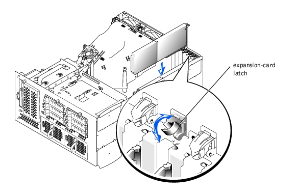
- Open the expansion-card latch (see Figure 6-8) and remove the filler bracket.
- Install the expansion card (see Figure 6-8):
- Position the expansion card so that the card-edge connector aligns with the
expansion-card connector on the system board.
- Insert the card-edge connector firmly into the expansion-card connector until the
card is fully seated.
- When the card is seated in the connector, close the expansion-card latch (see
Figure 6-8).
|
NOTE: SCSI cables connected from an expansion card to the SCSI backplane board
should be routed under the front fan assembly.
|
Figure 6-8. Installing an Expansion Card
- Reconnect all expansion-card cables, including those for the new card.
See the documentation that came with the card for information about its cable connections.
|
NOTE: If the expansion card you are installing is of a different operating speed as the card
already installed on the same PCI bus, all expansion cards on that bus will operate at the
slower speed.
|
- Replace the front fan assembly (see "Replacing the Front Fan Assembly").
- Replace the cover (see "Replacing the Cover" in "Troubleshooting Your System").
|
|
CAUTION: Before you perform this procedure, you must turn off the system and
disconnect it from its power source. For more information, see "Safety First—For
You and Your System" in "Troubleshooting Your System."
|
|
|
CAUTION: See "Protecting Against Electrostatic Discharge" in the safety
instructions in your System Information document.
|
- Open the bezel (see "Removing the Bezel" in "Troubleshooting Your System").
- Turn off the system, including any attached peripherals, and disconnect the system
from the electrical outlet.
- Remove the cover (see "Removing the Cover" in "Troubleshooting Your System").
- Disconnect all expansion-card cables.
- Remove the front fan assembly (see "Removing the Front Fan Assembly").
- Release the expansion card:
- Open the expansion-card latch (see Figure 6-8).
- Grasp the expansion card by its top corners, and carefully remove it from the
expansion-card connector.
- If you are removing the card permanently, install a metal filler bracket over the empty
expansion slot opening and close the expansion-card latch.
 |
NOTICE: You must install a filler bracket over an empty expansion slot to maintain Federal
Communications Commission (FCC) certification of the system. The brackets also keep dust and
dirt out of the system and aid in proper cooling and airflow inside the system.
|
- Reconnect all expansion-card cables.
- Replace the front fan assembly (see "Replacing the Front Fan Assembly").
- Replace the cover (see "Replacing the Cover" in "Troubleshooting Your System").
The six memory module connectors on the system board can accommodate from 256 MB to 6 GB of registered memory modules. The memory module connectors are arranged in pairs which consist of three banks (Bank 1 – Bank 3).
The system is upgradable to 6 GB by installing combinations of 128-, 256-, 512-MB, and 1-GB registered DDR SDRAM modules. You can purchase memory upgrade kits as needed.
|
NOTICE: The memory modules must be PC-2100 compliant.
|
Starting with the connector nearest the side of the chassis, the memory module connectors are labeled "DIMM1A" through "DIMM3B" (see Figure A-3). When you install memory modules, follow these guidelines:
- You must install memory modules in matched pairs.
- Install a pair of memory modules in connector DIMM1A and DIMM1B before installing a second pair in connectors DIMM2A and DIMM2B, and so on.
Figure 6-9. Memory Module Sockets
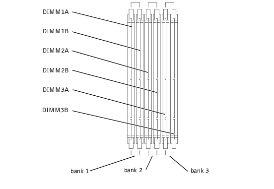
Table 6-3 lists several sample memory configurations based on these guidelines.
Table 6-3. Sample Memory Module Configurations
|
Total Desired
Memory
|
Bank 1
|
Bank 2
|
Bank 3
|
|---|
|
A
|
B
|
C
|
D
|
E
|
F
|
|---|
256 MB | 128 MB | 128 MB | None | None | None | None |
512 MB | 256 MB | 256 MB | None | None | None | None |
1 GB | 512 MB | 512 MB | None | None | None | None |
2 GB | 512 MB | 512 MB | 512 MB | 512 MB | None | None |
2 GB | 1 GB | 1 GB | None | None | None | None |
3 GB | 1 GB | 1 GB | 512 MB | 512 MB | None | None |
6 GB | 1 GB | 1 GB | 1 GB | 1 GB | 1 GB | 1 GB |
|
|
CAUTION: Before you perform this procedure, you must turn off the system and
disconnect it from its power source. For more information, see "Safety First—For
You and Your System" in "Troubleshooting Your System."
|
|
|
CAUTION: See "Protecting Against Electrostatic Discharge" in the safety
instructions in your System Information document.
|
- Open the bezel (see "Removing the Bezel" in "Troubleshooting Your System").
- Turn off the system, including any attached peripherals, and disconnect the system
from the electrical outlet.
- Remove the cover (see "Removing the Cover" in "Troubleshooting Your System").
- Remove the cooling shroud (see "Removing the Cooling Shroud").
- Install or replace the memory module pairs as necessary to reach the desired memory
total (see "Installing Memory Modules" and "Removing Memory Modules").
See Figure A-3 to locate the memory module connectors.
- Replace the cooling shroud (see "Replacing the Cooling Shroud").
- Replace the cover (see "Replacing the Cover" in "Troubleshooting Your System").
- Reconnect the system to its electrical outlet and turn the system on, including any
attached peripherals.
After the system completes the POST routine, it runs a memory test.
The system detects that the new memory does not match the system configuration information, which is stored in NVRAM. The monitor displays an error message that ends with the following words:
Press <F1> to continue; <F2> to enter System Setup
- Press <F2> to enter the System Setup program, and check the System Memory
setting.
The system should have already changed the value in the System Memory setting to reflect the newly installed memory.
- If the System Memory value is incorrect, one or more of the memory modules may not
be installed properly. Repeat steps 1 through 8, ensuring that the memory modules are
firmly seated in their connectors.
- Run the system memory test in system diagnostics.
|
|
CAUTION: Before you perform this procedure, you must turn off the system and
disconnect it from its power source. For more information, see "Safety First—For
You and Your System" in "Troubleshooting Your System."
|
|
|
CAUTION: See "Protecting Against Electrostatic Discharge" in the safety
instructions in your System Information document.
|
- Open the bezel (see "Removing the Bezel" in "Troubleshooting Your System").
- Turn off the system, including any attached peripherals, and disconnect the system
from the electrical outlet.
- Remove the cover (see "Removing the Cover" in "Troubleshooting Your System").
- Remove the cooling shroud (see "Removing the Cooling Shroud").
- Locate the memory module connectors in which you will install a memory module
(see Figure A-3).
- Press down and outward on the memory module connector ejectors, as shown in
Figure 6-10, to allow the memory module to be inserted into the connector.
Figure 6-10. Removing and Installing a Memory Module
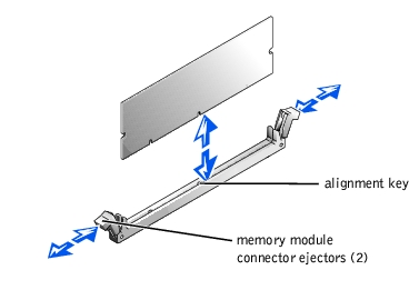
- Align the memory module's edge connector with the alignment key, and insert the
memory module in the connector (see Figure 6-10).
The memory module connector has an alignment key that allows the memory module to be installed in the connector in only one way.
- Press down on the memory module with your thumbs while pulling up on the ejectors
with your index fingers to lock the memory module into the connector (see
Figure 6-10).
When the memory module is properly seated in the connector, the memory module connector ejectors should align with the ejectors on the other connectors with memory modules installed.
- Repeat steps 5 through 7 of this procedure to install the remaining memory modules.
- Perform steps 6 through 10 of the procedure in "Performing a Memory Upgrade."
|
|
CAUTION: Before you perform this procedure, you must turn off the system and
disconnect it from its power source. For more information, see "Safety First—For
You and Your System" in "Troubleshooting Your System."
|
|
|
CAUTION: See "Protecting Against Electrostatic Discharge" in the safety
instructions in your System Information document.
|
- Open the bezel (see "Removing the Bezel" in "Troubleshooting Your System").
- Turn off the system, including any attached peripherals, and disconnect the system
from the electrical outlet.
- Remove the cover (see "Removing the Cover" in "Troubleshooting Your System").
- Remove the cooling shroud (see "Removing the Cooling Shroud").
- Locate the memory module connectors from which you will remove memory modules
(see Figure A-3).
- Press down and outward on the memory module connector ejectors until the memory
module pops out of the connector (see Figure 6-10).
- Repeat steps 4 and 5 of this procedure to remove any other memory modules.
- Perform steps 6 through 10 of the procedure in "Performing a Memory Upgrade."
To take advantage of future options in speed and functionality, you can add a second microprocessor or replace either the primary or secondary microprocessor.
|
NOTE: The second microprocessor must be of the same type as the first. If the two
microprocessors are different speeds, both will operate at the speed of the slower
microprocessor.
|
Each microprocessor and its associated cache memory are contained in a PGA package that is installed in a ZIF socket on the system board. A second ZIF socket accommodates a secondary microprocessor.
|
NOTE: In a single microprocessor system, the microprocessor must be installed in the
PROC 1 socket.
|
- A microprocessor
- A heat sink
- Two securing clips
- A VRM, if adding a second microprocessor
|
|
CAUTION: Before you perform this procedure, you must turn off the system and
disconnect it from its power source. For more information, see "Safety First—For
You and Your System" in "Troubleshooting Your System."
|
|
|
CAUTION: See "Protecting Against Electrostatic Discharge" in the safety
instructions in your System Information document.
|
- Open the bezel (see "Removing the Bezel" in "Troubleshooting Your System").
- Turn off the system, including any attached peripherals, and disconnect the system
from the electrical outlet.
- Remove the cover (see "Removing the Cover" in "Troubleshooting Your System").
- Remove the cooling shroud (see "Removing the Cooling Shroud").
- Remove the back fan assembly (see "Removing the Back Fan Assembly"). If you are
installing a second microprocessor, go to step 9.
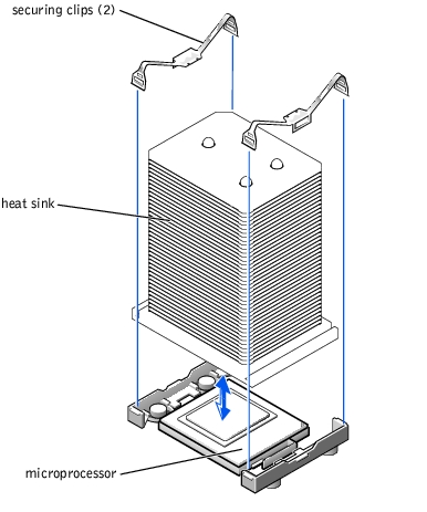
- Remove the microprocessor heat sink:
- Press down on the heat-sink securing clips to release the clips from the retaining
tabs on the ZIF socket (see Figure 6-11).
- Remove the heat-sink securing clips.
|
|
CAUTION: The microprocessor and heat sink can become extremely hot. Be sure
the microprocessor has had sufficient time to cool before handling.
|
|
NOTICE: Never remove the heat sink from a microprocessor unless you intend to remove the
microprocessor. The heat sink is required to maintain proper thermal conditions.
|
- Lift the heat sink out of the chassis and place it on its side.
Figure 6-11. Removing and Replacing a Heat Sink
- Pull the socket release lever straight up until the microprocessor is released (see
Figure 6-12).
- Lift the microprocessor out of the socket and leave the release lever up so that the
socket is ready for the new microprocessor.
|
NOTICE: Be careful not to bend any of the pins when removing the microprocessor. Bending
the pins can permanently damage the microprocessor.
|
Figure 6-12. Removing and Replacing a Microprocessor

- Unpack the new microprocessor.
If any of the pins on the microprocessor appear bent, see "Getting Help" for instructions on obtaining technical assistance.
- Ensure that the release lever on the microprocessor socket is in the upright position.
- Align pin 1 on the microprocessor (see Figure 6-12) with pin 1 on the microprocessor
socket.
|
NOTE: No force is needed to install the microprocessor in the socket. When the
microprocessor is aligned correctly, it should drop into the socket.
|
- Install the microprocessor in the socket (see Figure 6-12).
|
NOTICE: Positioning the microprocessor incorrectly can permanently damage the
microprocessor and the system when you turn on the system. When placing the microprocessor
in the socket, be sure that all of the pins on the microprocessor go into the corresponding holes.
Be careful not to bend the pins.
|
- When the microprocessor is fully seated in the socket, rotate the socket release lever
back down until it snaps into place, securing the microprocessor.
- Place the new heat sink on top of the microprocessor (see Figure 6-11).
- Orient the securing clips as shown in Figure 6-11.
- Hook the end of the clips without the latch to the tab on the edge of the socket.
- Push down and pivot the securing clip latch until the hole on the clip latches onto the
ZIF socket tab.
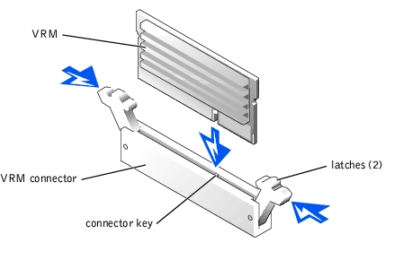
- If you are adding a second microprocessor, you must install a VRM in the VRM 2
connector, pushing down firmly to make sure that the latches engage (see
Figure 6-13).
Figure 6-13. Installing the VRM
- Replace the back fan assembly (see "Replacing the Back Fan Assembly").
- Replace the cooling shroud (see "Replacing the Cooling Shroud").
- Replace the cover (see "Replacing the Cover" in "Troubleshooting Your System").
- Reconnect the system to its electrical outlet and turn the system on, including any
attached peripherals.
- Enter the System Setup program, and ensure that the microprocessor options match
the new system configuration (see "Using the System Setup Program" in your User's
Guide).
As the system boots, it detects the presence of the new microprocessor and automatically changes the system configuration information in the System Setup program. If you installed a second microprocessor, a message similar to the following appears:
Two 2.2 GHZ Processors, Processor Bus: 400 MHz, L2 cache
512 KB Advanced
If only one microprocessor is installed, a message similar to the following appears:
One 2.2 GHz Processor, Processor Bus: 400 MHz, L2 cache
512 KB Advanced
- Confirm that the top line of the system data area in the System Setup program
correctly identifies the installed microprocessor(s) (see "Using the System Setup
Program" in your User's Guide).
- Exit the System Setup program.
- Run the system diagnostics to verify that the new microprocessor is operating
correctly.
See "Running System Diagnostics" for information on running the diagnostics and troubleshooting any problems that may occur.
The system battery is a 3.0-volt (V), coin-cell battery.
|
|
CAUTION: Before you perform this procedure, you must turn off the system and
disconnect it from its power source. For more information, see "Safety First—For
You and Your System" in "Troubleshooting Your System."
|
|
|
CAUTION: There is a danger of a new battery exploding if it is incorrectly
installed. Replace the battery only with the same or equivalent type
recommended by the manufacturer. Discard used batteries according to the
manufacturer's instructions. See the System Information document for
additional information.
|
|
|
CAUTION: See "Protecting Against Electrostatic Discharge" in the safety
instructions in your System Information document.
|
- Open the bezel (see "Removing the Bezel" in "Troubleshooting Your System").
- Turn off the system, including any attached peripherals, and disconnect the system
from the electrical outlet.
- Remove the cover (see "Removing the Cover" in "Troubleshooting Your System").
- Remove any expansion cards that are installed above the system battery (see
"Removing an Expansion Card").
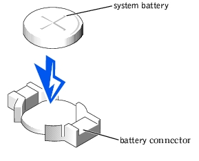
- Remove the system battery (see Figure 6-14).
See Figure A-3 to locate the system battery on the system board.
You can pry the system battery out of its connector with your fingers or with a blunt, nonconductive object such as a plastic screwdriver.
- Install the new system battery with the side labeled "+" facing up (see Figure 6-14).
Figure 6-14. Removing and Installing the System Battery
- Replace any expansion cards that were removed in step 3 (see "Installing an Expansion
Card").
- Replace the cover (see "Replacing the Cover" in "Troubleshooting Your System").
- Reconnect the system to its electrical outlet and turn the system on, including any
attached peripherals.
- Enter the System Setup program to confirm that the battery is operating properly (see
"Using the System Setup Program," in the User's Guide).
- Enter the correct time and date in the System Setup program's Time and Date fields.
- Exit the System Setup program.
- To test the newly installed battery, turn off the system and disconnect it from the
electrical outlet for at least an hour.
- After an hour, reconnect the system to its electrical outlet and turn it on.
- Enter the System Setup program and if the time and date are still incorrect, see
"Getting Help" for instructions on obtaining technical assistance.
Back to Contents Page