 Overview
Dell OpenManage™ Server Administrator Version 1.4 User's Guide
Adding and Configuring RAC Users
Configuring an Existing RAC User
Configuring the RAC Network Properties
Configuring the RAC Alert Properties
Configuring DRAC III Dial-in (PPP) Users and Modem Settings
Configuring the RAC Remote Features Properties
Accessing and Using a Remote Access Controller
The Server Administrator Remote Access Service provides a complete remote system management solution for SNMP- and CIM-instrumented systems equipped with a Dell™ Remote Access Card (DRAC) III, a DRAC III/XT, an Embedded Remote Access (ERA) controller, an ERA Option (ERA/O) card, or an ERA/MC controller. These hardware and software solutions are collectively known as remote access controllers (RACs).
The Remote Access Service provides remote access to an inoperable system, allowing you to get the system up and running as quickly as possible. The Remote Access Service also provides alert notification when a system is down and allows you to remotely restart a system. Additionally, the Remote Access Service logs the probable cause of system crashes and saves the most recent crash screen.
You can log into the Remote Access Service through the Server Administrator home page or by directly accessing the controller's IP address using a supported browser.
See the Server Administrator Command Line Interface User's Guide and the Dell Remote Access Controller Racadm User's Guide for information about running the Remote Access Service from the command line.
When using the Remote Access Service, you can click Help on the global navigation bar for more detailed information about the specific window you are viewing. Remote Access Service help is available for all windows accessible to the user based on user privilege level and the specific hardware and software groups that Server Administrator discovers on the managed system.
 |
NOTE: The Remote Access Service is not available on modular systems. You must directly connect to the remote access controller (RAC) on a modular system. See the Dell Embedded Remote Access/MC Controller User's Guide for more information. |
|
NOTE: See the Dell Remote Access Controller Installation and Setup Guide for complete information about installing and configuring a DRAC III, a DRAC III/XT, or an ERA/O controller, configuring an ERA controller, and using a RAC to remotely access an inoperable system. See the Dell Embedded Remote Access/MC Controller User's Guide for complete information about configuring and using an ERA/MC controller to remotely manage and monitor your modular system and its shared resources through a network. |
The managed system must have a RAC installed to use the Remote Access Service.
For a list of specific hardware requirements for your RAC, see the readme file for your remote access controller on the Systems Management CD and the Dell Remote Access Controller Installation and Setup Guide or the Dell Embedded Remote Access/MC Controller User's Guide on the documentation CD.
|
NOTE: The RAC software is installed as part of the Express Setup and Custom Setup installation options when installing managed system software from the Systems Management CD, provided that the managed system meets all of your RAC's installation prerequisites. See the appropriate RAC documentation for complete software and hardware requirements. |
The managed system must have the RAC software installed. See the Dell Remote Access Controller Installation and Setup Guide or the Dell Embedded Remote Access/MC Controller User's Guide for a complete list of software installation prerequisites.
|
NOTE: The RAC software is installed as part of the Express Setup and Custom Setup installation options when installing managed system software from the Systems Management CD, provided that the managed system meets all of your RAC's installation prerequisites. See the appropriate RAC documentation for complete software and hardware requirements. |
|
NOTE: For systems running supported Red Hat Linux operating systems, the Remote Access Service does not support Netscape Navigator. |
|
NOTE: You must have Admin privileges in Server Administrator to use the Remote Access Service. |
The RAC can store information for up to 16 users. The Remote Access Service provides security by requiring a user to provide a user name and password prior to establishing a remote connection. The Remote Access Service can also provide paging services to notify users if the system crashes, loses power, or experiences a defined list of other events. Paging services are only available for DRAC III cards.
To create a RAC user, perform the following steps:
The Remote Access Controller Users window appears.
The Add Remote Access Controller User window appears.
Traps enable you to configure the RAC to respond to alert conditions from the system's ESM hardware or to other conditions such as operating system crashes or power failures.
The first (left-most) column of check boxes corresponds to the severity level Informational, the second column corresponds to the severity level Warning, and the third column corresponds to the severity level Critical. The last seven events can only report the severity level Informational.
Server Administrator returns to the Users tab. The user you just created and configured is displayed in the User Name list.
|
NOTE: You must have Admin privileges in Server Administrator to use the Remote Access Service. |
To configure a RAC user, perform the following steps:
The Remote Access Controller Users window appears.
Traps enable you to configure the RAC to respond to alert conditions from the system's ESM hardware or to other conditions such as operating system crashes or power failures.
The first (left-most) column of check boxes corresponds to the severity level Informational, the second column corresponds to the severity level Warning, and the third column corresponds to the severity level Critical. The last seven events can only report the severity level Informational.
Server Administrator returns you to the Users tab.
|
NOTE: You must have Admin privileges in Server Administrator to use the Remote Access Service. |
Your RAC contains an integrated 10BASE-T/100BASE-T Ethernet NIC and supports TCP/IP. The NIC has a default address of 192.168.20.1 and a default gateway of 192.168.20.1.
|
NOTE: If your RAC is configured to the same IP address as another NIC on the same network, an IP address conflict occurs. The RAC stops responding to network commands until the IP address is changed on the RAC. The RAC must be reset even if the IP address conflict is resolved by changing the IP address of the other NIC. |
|
NOTE: Changing the IP address of the RAC causes the RAC to reset. If SNMP polls the RAC before it initializes, a temperature warning is logged because the correct temperature is not transmitted until the RAC is initialized. |
To configure the network properties of your RAC, perform the following steps:
The Configure Network Properties window appears.
RACs can be configured to respond to alert conditions from the system's ESM or to other conditions such as operating-system crashes or power failures.
RACs offer the following types of alert actions:
|
NOTE: You must have Admin privileges in Server Administrator to use the Remote Access Service. |
To configure the Remote Access Service alert properties, perform the following steps:
The first (left-most) column of check boxes corresponds to the severity level Informational, the second column corresponds to the severity level Warning, and the third column corresponds to the severity level Critical. The last seven events can only report the severity level Informational.
Dial-in (PPP) users and modem features are currently only available for the DRAC III.
|
NOTE: You must have Admin privileges in Server Administrator to use the Remote Access Service. |
When preset, dial-in (PPP) users call a DRAC III, the demand dial-out entry causes the Remote Access Service to disconnect and call the management station back at a preset number. Upon callback, users must provide their RAC user authentication to access the Remote Access Service.
|
NOTE: The RAC managed system software uses a PPP connection to talk to the installed RAC. The IP address for this PPP connection is 192.168.234.235. It is possible that this network IP address could already be in use by other systems or applications. If this situation occurs, the PPP connection fails to operate. If this address is already in use, the user is required to change the managed-system PPP client IP address to a different number. To change the managed-system PPP server IP address to use another network so that conflicts do not occur, you must use the racadm utility. See the Dell Remote Access Controller Racadm User's Guide for information about using the racadm utility. |
To add a demand dial-out entry, perform the following steps:
|
NOTE: You must have Admin privileges in Server Administrator to use the Remote Access Service. |
This subsection describes how to add and configure a dial-in (PPP) user. After dial-in users are authenticated, they must enter the RAC user authentication at the remote access controller login screen to access the DRAC III.
|
NOTE: The Server Administrator managed-system PPP client uses the 192.168.234.235 network to talk with the installed DRAC III. It is possible that this network IP address could already be in use by other systems or applications. If this situation occurs, the PPP connection fails to operate. If this address is already in use, the user is required to change the managed-system PPP client IP address to a different number. To change the managed-system PPP server IP address to use another network so that conflicts do not occur, you must use the racadm utility. See the Dell Remote Access Controller Racadm User's Guide for information about using the racadm utility. |
To add and configure dial-in users, perform the following steps:
This number is the one the Remote Access Service calls if Callback Type is set to Preset.
|
NOTE: You must have Admin privileges in Server Administrator to use the Remote Access Service. |
If your DRAC III kit includes the optional PCMCIA modem, you must configure the modem prior to use.
To configure the DRAC III modem, perform the following steps:
|
NOTE: You must have Admin privileges in Server Administrator to use the Remote Access Service. |
If the local boot image on the managed system has been corrupted, a RAC has the ability to boot its host server using a diskette boot image that it downloads from a Trivial File Transfer Protocol (TFTP) server. This feature is called remote floppy boot. A RAC can also update its firmware using a firmware image located on a TFTP server. This feature is called remote firmware update, and the process is similar to flashing a system BIOS.
To configure the remote floppy boot feature and the remote firmware update feature of your RAC, perform the following steps:
The Configure Network Properties window appears.
The Remote Properties window appears.
|
NOTE: You must have Admin privileges in Server Administrator to use the Remote Access Service. |
|
NOTE: See the Dell Remote Access Controller Installation and Setup Guide for more information about RAC security features. |
To configure your RAC security from the Server Administrator home page, click System® Main System Chassis® Remote Access Controller and then click the Security tab. Under the Security tab, you can perform CSR certificate management and set RAC user login authentication options.
Use the Certificate Management window to generate a certificate signing request (CSR), upload a server certificate or certificate authority (CA) certificate to the RAC firmware, or view an existing server certificate or CA certificate. From the Certificate Management window, the following options are available:
A CSR is a digital request to a CA for a secure server certificate. Secure server certificates ensure the identity of a remote system and ensure that information exchanged with the remote system cannot be viewed or changed by others. To ensure the security for your RAC, it is strongly recommended that you generate a CSR, submit the CSR to a CA, and upload the certificate returned from the CA.
A certificate authority is a business entity that is recognized in the IT industry for meeting high standards of reliable screening, identification, and other important security criteria. Examples of CAs include Thwate and VeriSign. Once the CA receives your CSR, they review and verify the information the CSR contains. If the applicant meets the CA's security standards, the CA issues a certificate to the applicant that uniquely identifies that applicant for transactions over networks and on the internet.
After the CA approves the CSR and sends you a certificate, you must upload the certificate to the RAC firmware. The CSR information stored on the RAC firmware must match the information contained in the certificate.
 |
NOTICE: Each new CSR overwrites any pervious CSR on the firmware. It is crucial that the CSR on the firmware matches the certificate returned from a CA. |
The Certificate Signing Request (CSR) Generation window appears.
A message appears stating that the CSR was successfully generated and giving the path where it was saved.
To upload your server certificate or CA certificate to the RAC firmware, you must designate the CSR type, designate the exact filename and file path, and click Upload.
The Upload Certificate window appears.
The selections are Server Certificate and CA Certificate.
|
NOTE: When you have a fully-qualified path or file name that contains spaces, you must place double quotation marks around the string. For example, if your file is contained in c:\security files\certificates\sslcert.cer, you must place the fully qualified path name and file name in double quotations because a space appears between "security" and "files." For example: "c:\security files\certificates\sslcert.cer". |
A message appears stating that the certificate was successfully uploaded to the RAC firmware.
The following information is included on both the View Server Certificate and View CA Certificate windows. See Table 6-1.
Table 6-1. Certificate Information
|
Attribute |
Value |
|---|---|
Type of certificate, either a server certificate or a CA certificate | |
Use the Remote Connect Authentication Options window to set RAC user login authentication options. You can configure the RAC to only allow login by users created thought the Remote Access Service (RAC users), or to allow RAC login by users created both through the Remote Access Service and through the local operating system.
The Certificate Management window appears.
The Remote Connect Authentication Options window appears. There are two configuration options, each proceeded by a check box.
The RAC Authentication check box is selected by default and cannot be deselected. This setting allows login to the RAC by users created through the RAC (RAC users).
Put a check in the Local Operating System Authentication check box to also allow login to the RAC by users created through the local operating system.
This section provides basic information about using a RAC to monitor and manage your system, including connecting to the RAC to access system and session information, managing the RAC configurations, and performing remote access functions on the managed system. This section includes the following topics:
To link to the Remote Access Service RAC Log in window from the Server Administrator home page, click the Main System Chassis object, click the Remote Access Controller object, click the Remote Connect tab, and then click Remote Connect. The RAC Log in window appears.
You can also link to the Remote Access Service RAC Log in window by accessing the RAC's IP address from a supported Web browser. Open your Web browser and type http://IP address in the address field and press <Enter> (where IP address is the IP address for the RAC). The RAC Log in window appears.
To log into the Remote Access Service RAC home page, perform the following steps:
This field is case sensitive. The default login name is root.
This field is case sensitive. The default password is calvin. You can also press <Tab> to navigate to this field.
Local RAC is the default entry.
To end your Remote Access Service session, click Log Out on the global navigation bar.
The Remote Access Service RAC home page defaults to the Summary window under the Properties tab.
Like the Server Administrator home page, the Remote Access Service RAC home page has three main areas:
Additionally, when you are logged into the Remote Access Service RAC home page, the RAC type, system model, and current user's user name are displayed in the top-right corner of the window.
Figure 6-1 shows a sample Remote Access Service RAC home page layout for a user logged in to an ERA. For more information about the Remote Access Service RAC home page layout, see "The Server Administrator Home Page."
Figure 6-1. Sample Remote Access Service RAC Home Page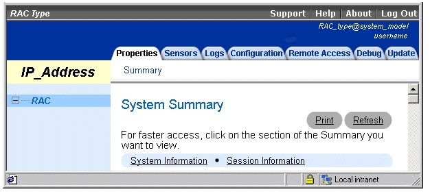
The status indicator icons graphically show the status of a sensor or component (as of the latest page refresh).
|
A green check mark indicates a healthy (normal) status condition. |
|
|
|
|
|
From the Remote Access Service RAC home page, you can access system and sessions information. To access system and session information for your RAC, click the Properties tab. The following options are available:
DSU+HH:MM:SS
After the managed system event system is initialized and exchanges local time information with the RAC, the time displayed is the local date and time. Local date and time appears in the following format:
YYYY-MM-DD HH:MM:SS GMT<+ | - >HH:MM
|
NOTE: The time zone is represented as hours and minutes east or west of GMT. West is negative, east is positive. |
2001-01-01 23:00:59 GMT - 14:30
|
NOTE: The Firmware Updated field remains blank until a firmware update is performed. |
|
NOTE: Watchdog provides the same functionality as automatic recovery. |
|
NOTE: A RAC supports up to 16 simultaneous sessions. |
From the Remote Access Service RAC home page, you can access sensor data. To access sensor information, click the Sensors tab. The following options are available:
Displays a summary of temperature and voltage values and status. Click the probe name for more information about that sensor.
Displays a summary of managed system sensors. For more information on a particular sensor, perform the following steps:
The selected sensor appears in the Sensors to Poll box on the right side of the screen. To remove the sensor from the Sensors to Poll list, click X.
|
NOTE: You can monitor up to eight sensors at a time. |
A summary of the eight sensors is displayed.
After clicking the probe name, a graphical temperature gauge is displayed that identifies the current reading and normal operating threshold for the probe. The thresholds are also displayed as numerical values in the top-right corner of the sensor details box. For definitions of the RAC status indicator icons, see "Status Indicator Icons." For definitions of the sensor thresholds, see "Sensor Thresholds."
From the Remote Access Service RAC home page, you can access RAC logs and system logs. To access log information, click the Logs tab. A RAC provides access to logs that are generated by both the RAC and the managed system:
The POST log is generated by the managed system and lists POST events recorded during the most recent system boot. To access the POST log from the Logs window, click POST.
The contents of the POST log are written by the BIOS of the managed system and are overwritten during each system boot. The POST log displays the following information:
The RAC log is a persistent log maintained in the RAC firmware. To access the RAC log from the Logs window, click RAC.
The log contains a list of user actions (such as log in and log out) and alerts issued by the RAC. The oldest entries are overwritten when the log becomes full. If the RAC loses communication with the managed system, all entries that the RAC would have added to the Hardware log (such as power failure or RAC sensor alert) are added to the RAC log until communication is re-established.
The RAC log displays the following information:
To clear the RAC log of all entries, click Clear Log in the top-right corner of the screen.
The hardware log displays system-critical events that occur on the managed system. To access the hardware log from the Logs window, click Hardware.
The hardware log is generated by ESM instrumentation on the managed system and by the RAC if you have configured it to monitor any managed system events. It includes date, time, and a description of each event generated by the ESM and other instrumentation on the managed system.
The hardware log displays the following information:
The boot path analysis log displays operations performed and problems encountered during system boot. To access the boot path analysis log from the Logs window, click Boot Path Analysis.
The boot path analysis log displays the following information:
The Last Crash Screen option displays the most recent crash screen, allowing you to obtain information on events leading up to the system crash. This information is saved in RAC memory and made available for remote display. To access Last Crash Screen from the Remote Access window, click Last Crash Screen.
The Last Crash Screen option works in conjunction with the managed system's auto recovery (watchdog timer) functions. In order to capture a last crash screen, the system's Auto Recovery option must be set to either Reboot System or PowerCycle System.
To set the Auto Recovery option, perform the following steps:
|
NOTE: If no crash screen is available, the message No previously captured last crash screen is available is displayed. |
From the Remote Access Service RAC home page, you can configure sensor poll rates. To access the RAC configuration features, click the Configuration tab.
The Poll Rates option allows you to configure the time interval for the RAC to update specific information. To access the poll rates features from the Configuration window, click Poll Rates.
Poll Rate configuration allows you to set the rate at which the RAC samples status information from its integrated sensors (for DRAC IIIs only) or from the ESM sensors on the managed system. It also determines how often the RAC retrieves system information from the managed system. Use the Poll Rates option to change the Session Timeout Value and to change the frequency with which the following fields are updated:
|
NOTE: Poll rate settings are retained only for the current session and do not apply to any other user sessions. |
To access the RAC Remote Access functions, click the Remote Access tab on the Remote Access Service RAC home page. From the Remote Access window, the following options are available:
A RAC allows you to remotely perform a variety of power management actions on the managed system, such as graceful shutdown through the operating system or a hard reset (equivalent to pressing the reset button). To access the server reset options from the Remote Access window, click Server Reset Options.
From the Server Reset Options window, you can configure the following resets for the managed system by selecting from the following reset options and clicking Apply Reset Option:
|
NOTE: If the Graceful Server Shutdown or the Graceful Server Restart commands are issued to systems running a supported Novell® NetWare® operating system, an MS- DOS® prompt is displayed. This prompt indicates that the operating system has been shut down, but the system must be manually turned off and on using the power button. If either of these commands are issued to systems running a supported Red Hat Linux operating system, the operating system shuts down and then displays a message indicating that it is okay to manually turn the system off or on using the power button. |
|
NOTE: When using Graceful Server Restart, Reset, and Server Power Cycle options with console redirection, you must allow approximately 2 minutes for the managed system to restart before attempting to log back into the system remotely. This time allows the managed system time to reestablish a connection with the console redirection service. |
The Remote Floppy Boot option, available for supported Windows and Red Hat Linux operating systems, allows you to boot a managed system from a bootable floppy image stored on a TFTP server or on the RAC. To access the Remote Floppy Boot option from the Remote Access window, click Remote Floppy Boot.
Using the Remote Floppy Boot option, you can boot a managed system into a temporary command-prompt environment to run diagnostic programs or utilities. After the managed system boots, you can use console redirection to interact with the command-prompt environment.
Before using the Remote Floppy Boot option, you must first do one of the following:
|
NOTE: You must have a TFTP server running to download bootable floppy image files to the RAC. Many TFTP servers are available both commercially or free on the Internet. If you do not already have a TFTP server running, it is recommended that you use one of the TFTP servers on the Microsoft website at www.microsoft.com. |
|
NOTE: The maximum size of the image used for remote floppy boot is 1.44 MB. |
The following subsections provide procedures for using the RemoteFloppyUtility.exe and remotefloppy.exe utilities to create an image file for remote floppy boot.
To create or copy the bootable floppy image file using the GUI utility, perform the following steps:
The default bootable floppy image filename is bootimg.bin.
The default diskette drive letter is A.
The Progress Indicator shows the percent complete of the transfer, and the Status window shows status and error messages that may occur during the transfer.
To create or copy the bootable floppy image file using the command-line utility, perform the following steps:
A command-prompt window opens.
This command returns the following text in the command prompt window:
Usage: remotefloppy.exe <-c | -p> [-d <drive:>] [-f filename] [-v] [-h]
-c Create file image of a target disk floppy.
-p Put existing file image onto a target disk floppy.
-d <drive> Drive letter containing floppy disk.
The drive letter must contain ':'.
The default drive letter is "a:".
-f <filename> Filename of boot file. The default filename is "BOOTIMG.BIN".
-v Version information will be displayed to the user.
-h Usage syntax will be displayed to the user.
The -c (create) and -p (put) parameters are required and mutually exclusive; you must select one or the other. The -d, -f, -v, and -h parameters are all optional. The -v and -h parameters are used alone to display the version of the utility and the help screen.
For example, if you want to create an image file named BOOTIMG.BIN from a bootable floppy image residing on logical drive A, type the following command:
Using another example, if you want to put an image file named BOOT1.BIN on logical drive B, type the following command:
After you create or put the desired.bin files, close the command prompt window.
The following commands are used to create and copy the boot image file from a Linux command shell window.
To copy the diskette image to a file, type the following line at the shell prompt and press <Enter>:
dd if=/dev/fd0 of=<filename> bs=1440k
where <filename> is the name of the output file.
To copy an image file to a diskette, type the following line at the shell prompt and press <Enter>:
dd if=<filename> of=/dev/fd0 bs=1440k
|
NOTE: Before using this procedure, you must create a bootable floppy image and make it available locally or on a TFTP server. See the previous sections for more information. |
To boot a managed system from a bootable floppy image, perform the following steps:
The following is an example of status text:
Remote Floppy Enabled: No
Image Loaded: No
Boot From: Remote Floppy, One Time
Mode: Read Only
Before you can initiate a remote floppy boot, you must load the bootable floppy image and then enable the remote floppy boot feature.
A feedback (progress) message appears, followed by the remote floppy boot status. Remote Floppy Enabled should now read Yes.
At the top of the Remote Floppy Boot window, select Insert Remote Floppy.
A Command in progress message appears in the Status Text box, followed by the remote floppy boot status. Image Loaded should now read Yes.
|
NOTE: If at any time you want to save the bootable floppy image loaded into the RAC to a local file, select Copy Remote Floppy to Local System File, type a file path into the text box, and then click Apply Remote Floppy Boot Changes. |
In the Remote Floppy Boot window, select Set Remote Floppy Mode, select Read/Write, then click Apply Remote Floppy Boot Changes.
The Command in progress message appears, followed by the remote floppy boot status. Remote Floppy Mode should now read Read/Write.
You can now make modifications to the bootable floppy image, such as using the edit command to edit a batch file.
The Console Redirect option allows you to use the display, mouse, and keyboard on a local management station to control the corresponding devices on the remote managed system. To access the Console Redirect window from the Remote Access window, click Console Redirect.
|
NOTE: For graphical redirection, the managed system is performing the redirection process; therefore, a percentage of available microprocessor time is consumed when the process is active. It is recommended that you stop console redirection when not needed so that the system is available to perform its normal tasks. In addition, you should run the managed system in a low-resolution graphics mode, such as 800 x 600, and at a maximum of 256 colors to minimize the redirection task. |
|
NOTE: If a supported Novell NetWare operating system is running on the managed system, console redirection will be displayed as text-only. |
Console redirection provides the following functions:
|
NOTE: When switching between preboot and postboot screens, it may take several minutes for screen content to appear because the RAC must first connect to the RAC services on the managed system. |
The following buttons are available for use in the Console Redirect window:
If the managed system is running a supported NetWare operating system and has the RAC managed system software installed and running, the button appears as Enter Debug Mode. Use this button to enter Netware Debug Mode.
|
NOTICE: Entering Network Debug Mode will stop all services on the managed system. |
For Red Hat Linux, the VNC service (RACVNC) does not display the actual primary-system console of the managed system. Instead, RACVNC provides a virtual desktop that the remote user can use to execute systems management applications. This virtual desktop has all of the capabilities of any desktop that might be displayed at the actual managed system's console. This model is the generally accepted model for remote management for Red Hat Linux or UNIX®.
Only one shared systems management desktop is provided for console redirection through the RAC. Therefore, all remote, user-created console-redirection sessions through the RAC share the same desktop. If multiple management station users create console-redirection sessions at the same time, they simultaneously share the same desktop.
The Debug option allows you to configure and perform RAC debugging and diagnostic tests for network and paging on the RAC or managed system. To access RAC debug functions from the Remote Access Service RAC home page, click Debug. From the Debug window, the following options are available:
The Network Debug option allows you to perform debugging tasks for network and paging. To access the Network Debug window from the Debug window, click Network Debug. From the Network Debug window, the following information and options are available.
|
NOTE: After clicking one of the following options and clicking Submit, results of the debug tasks will be displayed in the Status Text box at the bottom of the page. |
|
NOTE: In the case of nonactive demand-dial connections, the ping option might report a failure because it usually takes more than 5 seconds to establish a demand-dial connection. If ping is retried after the connection is established, the packet is passed across the link. Even when the connection is established, it is still possible that the destination system is not reachable and able to respond to the ICMP echo. However, if the destination system is reachable and able to respond within 5 seconds, ping reports success on attempts after the connection is established. |
The Command Debug option allows you to manually input debug commands. To access the Command Debug window from the Debug window, click Command Debug. From the Command Debug window, you may use any of the following case-sensitive commands. To activate a command, click Submit. Command responses are displayed in the Status Text box at the bottom of the page.
|
NOTE: The debug selections in this group should only be used under the direction of qualified support personnel. |
The Trace Log option allows you to display the dump trace log and to set debugger trace levels to identify the types of messages being sent on the local network. To access the Trace Log window from the Debug window, click Trace Log. From the Trace Log window, select one of the following options:
The Status Check option allows you to perform diagnostic tasks on the RAC or managed system. To access the Status Check window from the Debug window, click Status Check. From the Status Check window, select one of the following options and click Submit.
|
NOTE: You can also update the RAC firmware using the Server Administrator Update Service. |
The Update option allows you to update the RAC firmware into the RAC flash memory. To access the firmware update from the Remote Access Service RAC home page, click the Update tab.
|
NOTE: The Firmware Updated field in the System Information window is blank until a firmware update is performed. |
The data included in the RAC firmware package includes the following:
|
NOTE: The firmware update retains the current RAC settings. |
|
NOTE: You must have a TFTP system running to download firmware image files to the RAC. Many TFTP systems are available both commercially and without cost on the Internet. If you do not already have a TFTP system running, Dell recommends that you use one of the TFTP systems that you can find on the Microsoft website at www.microsoft.com. |
|
NOTE: Before beginning the firmware update, you must first download the latest firmware version from Dell Support at support.dell.com and then upload it to a TFTP server. |
To update your RAC firmware, perform the following steps:
The RAC will reset after the firmware update is complete.