Dell™ PowerConnect™ 5224 Systems User's Guide
With web-based management, you can configure the PowerConnect 5224 Gigabit Ethernet Managed Switch and monitor the system using a web browser.
Most pages for the switch include the following buttons:
 |
NOTICE: For configuration changes to persist beyond the current session, you must either save the running-config file from the Switch/Configuration page or use the command line interface (CLI) command copy running-config startup-config. |
When you connect to the management mode of the switch with a web browser, a login screen is displayed. Enter a user name and password to access the switch's management mode.
 |
NOTE: The default user names are admin and guest, and the corresponding passwords are admin and guest. If you log in as guest (Normal Exec level), you can only view page information and change the guest password. If you log in as admin (Privileged Exec level), you can apply changes on all pages. |
The following menus are available from the web interface:
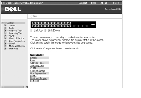
The System page contains a dynamic switch applet that displays the current status of the switch ports. The color of each switch port icon indicates its link status:
Clicking on any port icon displays the port configuration page.
The Switch page contains all system operations and general information. It includes links to the following options:
The General page contains links to the following pages:
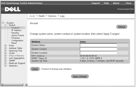
The Asset page contains the following information:
It also includes the following editable fields:
To save any changes you make in this page, click Apply Changes. If you don't want to save the changes, click Refresh.
The following table summarizes the equivalent CLI commands for items in the Switch/General/Asset page.
Console(config)#hostname Server Chassis 35
Console(config)#snmp-server contact Paul
Console(config)#snmp-server location WC-19
Console(config)#exit
Console#show system
System description: PowerConnect 5224
System OID string: 1.3.6.1.4.1.674.10895.4
System information
System Up time: 0 days, 0 hours, 14 minutes, and 17.93 seconds
System Name : Server Chassis 35
System Location : WC-19
System Contact : Paul
MAC address : 00-00-e8-00-00-02
Web server : enable
Web server port : 80
POST result :
--- Performing Power-On Self Tests (POST) ---
UART Loopback Test ..................... PASS
Timer Test ............................. PASS
CACHE Test.............................. PASS
DRAM Test .............................. PASS
I2C Initialization ..................... PASS
Runtime Image Check .................... PASS
PCI Device Check ....................... PASS
Switch Driver Initialization ........... PASS
------------------- DONE --------------------
Console#
The Health page contains the following information:
The power status is indicated by the following icons:
To reset these fields to their current value, click Refresh.

The following table summarizes the equivalent CLI command for items in the Switch/General/Health page.
|
Command |
Usage |
|---|---|
show version | Displays hardware and software version information for the system, as well as the unit's power status |
Console#show version
Unit1
Serial number :123457
Service tag :3
Hardware version :/2002
Number of ports :24
Master power status :up
Backup power status :up
Agent(master)
Unit id :1
Loader version :0.0.5.5
Boot rom version :0.0.6.0
Operation code version :0.2.0.0
Console#
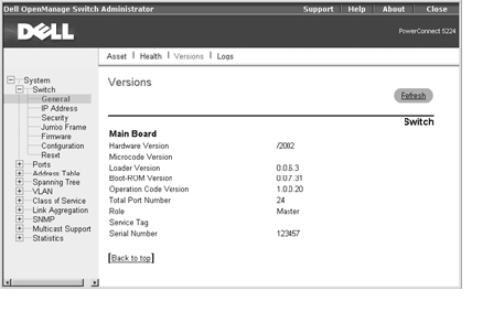
The Versions page contains the following fields:
The following table summarizes the equivalent CLI command for items in the Switch/General/Versions page.
|
Command |
Usage |
|---|---|
show version | Displays hardware and software version information for the system, as well as the unit's power status |
Console#show version
Unit1
Serial number :123457
Service tag :3
Hardware version :/2002
Number of ports :24
Master power status :up
Backup power status :up
Agent(master)
Unit id :1
Loader version :0.0.5.5
Boot rom version :0.0.6.0
Operation code version :0.2.0.0
Console#
The Logs page allows you to scroll through the logged system and event messages. The switch can store up to 2 kilobytes (KB) of log entries in temporary random access memory (RAM) (memory flushed on power reset) and up to 4 KB of entries in permanent flash memory.

The following table summarizes the equivalent CLI commands for items in the Switch/General/Logs page.
|
NOTE: The CLI allows you to configure and limit system messages that are logged to flash or RAM memory. The show logging command only displays the current logging configuration. |
The system log messages are categorized by severity into eight levels, from 0 (Emergencies) to 7 (Debugging). The CLI command logging history allows you to specify which messages are logged to RAM or flash memory. The default is for messages with severity levels of 0 to 3 to be logged to flash and levels 0 to 7 to be logged to RAM.
Severe error messages that are logged to flash memory are permanently stored in the switch to assist in troubleshooting network problems. Up to 4 KB of message entries can be stored in the flash memory, with older messages being overwritten first when this memory capacity has been exceeded.
Console#show logging flash
Syslog logging: Disable
History logging in FLASH: level errors
Console#
The IP Address page contains links to the following pages:
From the IP Address page, you can manage the IP-related information about the system. The page includes the following editable fields:
|
NOTICE: When DHCP or BOOTP has been used to set the IP information, the IP Address, Subnet Mask, and Gateway IP Address fields display the assigned values. |
The Management VLAN is the only VLAN through which you can gain management access to the switch. By default, all ports on the switch are members of VLAN 1, so a management station can be connected to any port on the switch. If other VLANs are configured and you change the Management VLAN, you may lose management access to the switch. In this case, you should reconnect the management station to a port that is a member of the Management VLAN. For more information on the Management VLAN, see "Management VLAN Access."
To save any changes you make in this page, click Apply Changes. If you don't want to save the changes, click Refresh.

The following table summarizes the equivalent CLI commands for items in the Switch/IP Address page.
Console(config)#interface vlan 1
Console(config-if)#ip address 192.168.1.5 255.255.255.0
Console(config-if)#exit
Console(config)#ip default-gateway 192.168.1.254
Console(config)#
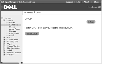
In the DHCP page, click Restart DHCP to release the current IP address and obtain a new one through DHCP.
|
NOTICE: If Restart DHCP is selected when IP settings have been configured statically, a warning message indicating that the IP Address Mode is not set to DHCP displays. |
The following table summarizes the equivalent CLI command for items in the Switch/IP Address/DHCP page.
|
Command |
Usage |
|---|---|
ip dhcp restart | Resubmits a DCHP client request |
The Security page contains links to the following information:
You should change the default passwords to be sure that your system is secure:
|
NOTE: The default user names are admin and guest, and the corresponding passwords are admin and guest. If you log in as guest (Normal Exec level), you can only view page information and change the guest password. If you log in as admin (Privileged Exec level), you can apply changes on all pages. |
The password entered is encrypted on the screen and is displayed as a sequence of asterisks (*).
To save any changes you make in this page, click Apply Changes. If you don't want to save the changes, click Refresh.

The following table summarizes the equivalent CLI commands for items in the Switch/Security/Passwords page.
|
NOTE: Only the CLI allows user names to be created and deleted. |
Console(config)#enable password level 15 0 admin
Console(config)#username bob access-level 15
Console(config)#username bob password smith
Console(config)#
Remote Authentication Dial-in User Service (RADIUS) is a system that uses a central server running RADIUS software to control access to RADIUS-aware switches on the network. A RADIUS server can be used to create a database of multiple user name/password pairs with associated privilege levels for each user or group that require management access to a switch using the console port, Telnet, or Internet.
When you are setting up privilege levels on the RADIUS server, level 0 allows Normal Exec access to the switch, and level 15 allows Privileged Exec access.
The RADIUS Settings page contains the following editable fields:
|
NOTE: The local switch user database must be set up through the CLI by manually entering user names and passwords. |
To save any changes you make in this page, click Apply Changes. If you don't want to save the changes, click Refresh.

The following table summarizes the equivalent CLI commands for items in the Switch/Security/RADIUS Settings page.
Console(config)#authentication login radius
Console(config)#radius-server host 192.168.1.25
Console(config)#radius-server port 181
Console(config)#radius-server key solvent
Console(config)#radius-server retransmit 5
Console(config)#radius-server timeout 10
Console(config)#
From the Jumbo Frame page, you can enable and disable jumbo frame support on the switch.
The switch provides more efficient large sequential data transfers by supporting jumbo frames up to 9000 bytes. Compared to standard Ethernet frames that run only up to 1500 bytes, using jumbo frames significantly reduces the per-packet overhead required to process protocol encapsulation fields.
To use jumbo frames, both the source and destination end nodes (such as a computer or server) must support jumbo frames. In addition, when the connection is operating at full duplex, all switches in the network between the two end nodes must be able to accept the extended frame size. For half-duplex connections, all devices in the collision domain must support jumbo frames.
To enable jumbo frame support on the switch, set the Jumbo Frame Support Status to Enabled.
|
NOTICE: Enabling jumbo frames on the switch limits the maximum threshold for broadcast storm control to 64 packets per second. |
To save any changes you make in this page, click Apply Changes. If you don't want to save the changes, click Refresh.

The following table summarizes the equivalent CLI command for items in the Switch/Jumbo Frame page.
|
Command |
Usage |
|---|---|
jumbo frame | Use this command to enable jumbo frames to be forwarded through the switch. Use the no form to disable jumbo frames. |
Console(config)#jumbo frame
Console(config)#
From the Firmware page, you can configure the system to download a new version of the management software. The switch can contain two software code files, one of which is set as the Start-Up file. This allows you to try a new version of the software without overwriting the previous version.
|
NOTE: The switch is shipped with one software code file installed (the filename is similar to PC5224_v1.00.00.00), which is set as the start- up file. |
The Firmware page contains the following fields:
It also contains the following editable fields:

The following table summarizes the equivalent CLI commands for items in the Switch/Firmware page.
|
NOTE: You cannot upload and download Boot-ROM files to a TFTP server using the CLI. You must use a direct terminal connection to the switch's console port and press <Ctrl><f> after the diagnostic test results. See "Downloading Firmware Through the Console Port." |
Console#copy tftp file
TFTP server ip address: 10.1.0.45
Choose file type:
1. config: 2. opcode: <1-2>: 2
Source file name: runtime
Destination file name: 0126.bix
/
Console#
From the Configuration page you can save and restore switch configuration settings.
|
NOTE: The switch is
shipped with one default
configuration file
(Factory_Default_ Config.cfg) installed, which is set as the start- up file. This file cannot be removed from the system. |
The Configuration page contains the following editable fields:
|
NOTICE: For configuration changes to persist beyond the current session, you must save the running-config file from this page, or use the CLI command copy running-config startup-config. |
|
NOTE: The CLI also allows you to copy files within the switch and replace a running configuration file without performing a reset. |


The following table summarizes the equivalent CLI commands for items in the Switch/Configuration web page.
Console#copy tftp startup-config
TFTP server ip address: 10.1.0.99
Source configuration file name: startup.01
Startup configuration file name [startup]:
/
Console#
Click Reset to reboot the switch. When prompted, confirm that you want to reset the switch.

The following table summarizes the equivalent CLI command for items in the Switch/Reset page.
|
Command |
Usage |
|---|---|
reload | Restarts the system |
Console#reload
System will be restarted, continue <y/n>? y
Console#
The Port Manager contains links to the following options:
On the Port Configuration page, you can view and edit port parameters. For each port number listed in the Port column, you can change the following parameters listed by column name on the screen:
|
NOTICE: If autonegotiation is disabled for an RJ-45 port, the auto- MDI/MDI-X pin signal configuration is also disabled. |

The following table summarizes the equivalent CLI commands for items in the Ports/Port Configuration page.
|
NOTICE: Flow control only works for ports connected to the same internal switch chip (ports 1 to 12 and ports 13 to 24). Cross-chip flow control does not work. |
Console(config)#interface ethernet 1/5
Console(config-if)#
Console(config-if)#description RD SW#3
Console(config-if)#no negotiation
Console(config-if)#speed-duplex 100half
Console(config-if)#flowcontrol
On the Trunk Configuration page, you can enable and disable the aggregate port links that have been created on the switch. To set up trunks and select port members, use the Link Aggregation page.
For each trunk number listed in the Trunk column, you can change the following parameters listed by column name on the screen:
To save any changes you make in this page, click Apply Changes. If you don't want to save the changes, click Refresh.

The following table summarizes the equivalent CLI commands for items in the Ports/Trunks Configuration page.
Console(config)#interface port-channel 1
Console(config-if)#
Console(config-if)#description RD SW#3
Console(config-if)#no negotiation
Console(config-if)#speed-duplex 100half
Console(config-if)#flowcontrol
In the Broadcast Control page, you can enable and disable broadcast control for all ports on the switch.
The Broadcast Control page contains the following information:
The Broadcast Control page also contains the following editable fields:
|
NOTICE: You can enable/disable broadcast storm control on a per-port basis, but the selected packet-per-second threshold applies to all ports on the switch. |
To save any changes you make in this page, click Apply Changes. If you don't want to save the changes, click Refresh.
|
NOTE: Broadcast control does not affect IP multicast traffic. |

The following table summarizes the equivalent CLI command for items in the Ports/Broadcast Control web page.
|
Command |
Usage |
|---|---|
switchport broadcast packet-rate rate | Configures broadcast storm control (applies to all ports) |
Console(config)#interface ethernet 1/5
Console(config-if)#switchport broadcast packet-rate 64
Console(config-if)#
From the Port Mirroring page, you can configure a port mirror session by setting a source and destination port pair. Port mirroring helps you debug a network.
|
NOTICE: You can configure only one port mirror session on the switch. The source and destination port have to be either both in the port range of 1 to 12 or both in the port range of 13 to 24. |
The following options are available:
|
NOTE: The source port and destination port speeds must match. Otherwise traffic may be dropped from the destination port. |
To add a new mirror session to the Sessions Table, first delete the current mirror session by selecting the session in the table and clicking Remove Mirror Session. Select the new source port, destination port, and traffic type, and then click Add Mirror Session.
|
NOTE: The source and destination ports must both either be in the range of 1 to 12 or 13 to 24. |

The following table summarizes the equivalent CLI commands for items in the Ports/Port Mirroring page.
|
Command |
Usage |
|---|---|
port monitor interface [rx | tx | both] | Configures a mirror session |
show port monitor [interface] | Displays mirror information |
Console(config)#interface ethernet 1/6
Console(config-if)#port monitor ethernet 1/5 both
Console(config-if)#
The Address Table page includes links to the following pages:
From the Static Addresses page, you can specify the Media Access Control (MAC) address and port number of systems that are to remain available to the switch for an indeterminate amount of time.
The following options are available:
To add a new address to the table, select the interface, MAC address, and VLAN, and then click Add Static Address. To delete an address from the table, select the table entry in the list box, and then click Remove Static Address.

The following table summarizes the equivalent CLI commands for items in the Address Table/Static Addresses page.
Console(config)#bridge 1 address 00-e0-29-94-34-de vlan 1 forward ethernet 1/1 delete-on-reset
Console(config)#
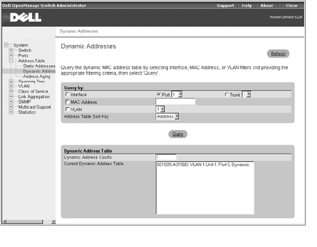
The Dynamic Address lookup table allows you to view the MAC addresses that are currently in the address database. When addresses are in the database, the packets intended for those addresses are forwarded directly to those ports. You can sort the table by interface, VLAN, and MAC address by selecting the sort key from the drop-down menu.
The Dynamic Addresses page contains the following options for querying the dynamic MAC address table:
The following table summarizes the equivalent CLI command for items in the Address Table/Dynamic Addresses page.
|
Command |
Usage |
|---|---|
show bridge bridge-group [interface] [address [mask]] [vlan vlan-id] [sort {address | vlan | interface}] | Allows you to view classes of entries in the bridge-forwarding database |
Console#show bridge 1
Interface Mac Address Vlan Type
--------- ----------------- ---- ---------------
Eth 1/11 00-10-b5-62-03-74 1 Learned
Console#
In the Address Aging page, you can specify the length of time an address stays available to the switch if it is not configured as static.
The Aging Time option sets the time before an address is purged from the system. You can change this value to any number between 17 and 2184. (The default is 300 seconds.)
To save any changes you make in this page, click Apply Changes. If you don't want to save the changes, click Refresh.

The following table summarizes the equivalent CLI command for items in the Address Tabled/Address Aging page.
|
Command |
Usage |
|---|---|
bridge-group bridge-group aging-time seconds | Sets the aging time for entries in the address table |
Console(config)#bridge-group 1 aging-time 300
Console(config)#
The Spanning Tree page contains links to pages that allow you to specify the parameters of the Spanning Tree Protocol:
The Bridge Settings page contains the following information:
From the Bridge Settings page, under Attributes, you can also enable and configure the following Spanning Tree parameters:
To save any changes you make in this page for the current session, click Apply Changes. If you don't want to save the changes, click Refresh.

The following table summarizes the equivalent CLI commands for items in the Spanning Tree/Bridge Settings page.
Console(config)#bridge 1 spanning-tree
Console(config)#bridge 1 forward-time 15
Console(config)#bridge 1 hello-time 2
Console(config)#bridge 1 max-age 20
Console(config)#bridge 1 priority 40000
In the Port Settings page, you can specify Spanning Tree parameters for each port. For each port number listed in the Port column, the following information is available:
The Port Settings page also contains the following editable fields:
|
NOTE: Use Fast Link if a device is connected to a port that requires network access immediately when the link comes up and cannot wait for a Spanning Tree resolution. |

The following table summarizes the equivalent CLI commands for items in the Spanning Tree/Port Settings page.
Console(config)#interface ethernet 1/5
Console(config-if)#bridge-group 1 path-cost 50
Console(config-if)#bridge-group 1 priority 0
Console(config-if)#bridge-group 1 portfast
On the Trunk Settings page, you can specify Spanning Tree parameters for each trunk. For each port number listed in the Trunk column, the following fields are available:
|
NOTE: Use Fast Link if a device is connected to a trunk that requires network access immediately when the link comes up and cannot wait for a Spanning Tree resolution. |

The following table summarizes the equivalent CLI commands for items in the Spanning Tree/Trunk Settings page.
Console(config)#interface port-channel 1
Console(config-if)#bridge-group 1 path-cost 50
Console(config-if)#bridge-group 1 priority 0
Console(config-if)#bridge-group 1 portfast
You can use virtual LANs (VLANs) to assign ports on the switch to any of up to 255 LAN groups. In conventional networks with routers, broadcast and multicast traffic is split up into separate domains. Switches do not inherently support broadcast domains, which can lead to broadcast storms in large networks. By using IEEE 802.1Q-compliant VLANs and GARP VLAN Registration Protocol (GVRP), you can organize any group of network nodes into separate broadcast domains, confining broadcast and multicast traffic to the originating group. This also provides a more secure and cleaner network environment. For more information on how to use VLANs, see "VLANs."
The VLAN page includes links to the following pages:
On the VLAN Membership page, you define VLAN groups. The following options are available:
The VLAN tagging option is a standard set by the IEEE to facilitate the spanning of VLANs across multiple switches. For more information, see "VLANs" and the IEEE Std 802.1Q-1998 Virtual Bridged Local Area Networks.
To save any changes you make in this page, click Apply Changes. If you don't want to save the changes, click Refresh.
See "VLAN Membership" for more information on VLAN members.
|
NOTE: If you remove a VLAN group with existing port members, the ports will rejoin the default VLAN in untagged mode. |

The following table summarizes the equivalent CLI commands for items in the VLAN/VLAN Membership page.
Console(config)#vlan database
Console(config-vlan)#vlan 105 name RD5 media ethernet
Console(config-vlan)#exit
Console(config)#interface ethernet 1/1
Console(config-if)#switchport allowed vlan add 105,7,9 tagged
Console(config-if)#exit
Console(config)#exit
Console#show vlan id 105
VLAN Name Status Ports/Channel groups
---- -------- --------- ------------------------------ ---
105 RD5 active Eth1/ 1 Eth1/ 2 Eth1/ 3 Eth1/ 4 Eth1/ 5
Eth1/ 6 Eth1/ 7 Eth1/ 8 Eth1/ 9 Eth1/10
Console#
On the Port Settings page, you can specify the default port VLAN ID (PVID) for each port on your switch. All untagged packets entering the switch are tagged by default with the ID specified by the port's PVID.
The Port Settings page is set up in a table format. For each port listed in the Port column, the following options are available:
To save any changes you make in this page, click Apply Changes. If you don't want to save the changes, click Refresh.

The following table summarizes the equivalent CLI commands for items in the VLAN/Port Settings page.
Console(config)#interface ethernet 1/1
Console(config-if)#switchport native vlan 3
Console(config-if)#switchport acceptable-frame-types tagged
Console(config-if)#switchport ingress-filtering
Console(config-if)#
On the Trunk Settings page, you can specify the default port VLAN ID (PVID) for ports that are configured as trunk members. When an untagged packet enters the switch, it is, by default, tagged with the ID specified by the port's PVID.
For each trunk listed in the Trunk column, the following options are available:
To save any changes you make in this page, click Apply Changes. If you don't want to save the changes, click Refresh.

The GVRP page allows you to globally enable GVRP (GARP VLAN Registration Protocol) for the switch. GVRP defines a way for switches to exchange VLAN information to register VLAN members on ports across the network. You can use GVRP to set up VLANs in the network without having to manually configure the VLANs on each switch. GVRP can reduce the possibility of errors and ensure consistency in VLAN configuration throughout the network.
If you enable GVRP on a port with a tagged or untagged static VLAN, GVRP sends advertisements (GVRP Bridge Protocol Data Units [BPDUs]) containing the VLAN's ID. Any connected GVRP-aware port receiving the advertisements can dynamically join the advertised VLAN. All GVRP dynamically-learned VLANs operate as tagged VLANs. A GVRP-enabled port only joins a VLAN when an advertisement for that VLAN is received on that specific port. A GVRP-enabled port forwards advertisements from other ports on the switch but does not join the advertised VLAN.
To implement GVRP in a network, you must first configure the static VLANs required on switches that are connected to computers, servers, and other devices, so that these VLANs can be propagated across the network. For other core switches in the network, enable GVRP on the links between these devices. You should also determine security boundaries in the network and configure GVRP settings to limit the VLAN propagation.
When GVRP is globally enabled for the switch, the default setting allows all the ports to transmit and receive VLAN advertisements, as well as automatically join VLANs. To control and limit the VLAN propagation in a network, you can disable GVRP on ports to prevent advertisements from being propagated, or to forbid ports from joining specific VLANs. The VLAN Membership page allows you to set ports as Forbidden, which prevents them from joining a VLAN through GVRP.
|
NOTICE: GVRP-learned VLANs on the switch do not have assigned IP addresses. Therefore, the management VLAN must be statically configured on all switches in the network before you implement GVRP. |
For more information on VLANs and GVRP see "VLANs."
|
NOTICE: GVRP must be globally enabled for the switch before you can individually enable GVRP for a specific port or trunk. |
To save any changes you make in this page, click Apply Changes. If you don't want to save the changes, click Refresh.

The following table summarizes the equivalent CLI commands for items in the VLAN/GVRP page.
|
Command |
Usage |
|---|---|
bridge-ext gvrp | Enables GVRP for the switch. Use the no form command to disable it. |
show gvrp configuration [interface] | Shows whether GVRP is enabled. |
Console(config)#bridge-ext gvrp
Console(config)#
Class of Service (CoS) allows you to assign priority to data packets when traffic in the switch is buffered due to congestion. This switch supports CoS by using four priority queues for each port. Data packets in a port's high-priority queue will be transmitted before packets in the lower-priority queues.
The Class of Service page allows you to set the default priority for each port or trunk, and to configure the mapping of frame priority tags to the switch's four priority queues. The page includes links to the following options:
|
NOTICE: The IEEE 802.1p tags specify eight levels of priority, from the lowest (0) to the highest (7). IP Precedence or IP DSCP values are mapped to these priority tag levels, and the priority levels are mapped directly to the switch's four traffic class queues. |
In the Port Settings page, you can specify the default port priority for each port on the switch. All packets entering the switch that are untagged (do not already have a priority value) are tagged with the specified default port priority and then sorted into the appropriate priority queue at the output port.
For each port listed in the Port column, you can assign the default port priority (from 0 to 7) to untagged frames received on the port. The default setting for ports is 0.

The following table summarizes the equivalent CLI command for items in the Class of Service/Port Settings page.
|
Command |
Usage |
|---|---|
switchport priority default default-priority-id | Sets a priority for the incoming untagged frames or the priority of frames received by the device connected to the specified interface |
Console(config)#interface ethernet 1/3
Console (config-if)#switchport priority default 5
On the Trunk Settings page, you can specify the default port priority for each port in a switch trunk. All packets entering the switch that are untagged (do not already have a priority value) are tagged with the specified default port priority and then sorted into the appropriate priority queue at the output port.
For each trunk listed in the Trunk column, you can assign the default port priority (from 0 to 7) to untagged frames received on any port in the trunk. The default setting is 0.

The following table summarizes the equivalent CLI command for items in the Class of Service/Trunk Settings page.
|
Command |
Usage |
|---|---|
switchport priority default default-priority-id | Sets a priority for the incoming untagged frames or the priority of frames received by the device connected to the specified interface |
Console(config)#interface port-channel 2
Console (config-if)#switchport priority default 5
On the Traffic Classes page, you can configure the mapping of frame priority tags to each port's four CoS priority queues.
Each IEEE 802.1p priority level (from 0 to 7) listed in the Priority column can be mapped to one of the switch's four traffic class queues (from 0 to 3). The number 0 represents a low priority and higher values represent higher priorities.

The following table summarizes the equivalent CLI commands for items in the Class of Service/Traffic Classes page.
Console(config)#queue cos-map 0 0 1 2
Console(config)#queue cos-map 1 3
Console(config)#queue cos-map 2 4 5
Console(config)#queue cos-map 3 6 7
Console#show queue cos-map
Information of Eth 1/1
Queue ID Traffic class
-------- -------------
0 0 1 2
1 3
2 4 5
3 6 7
.
.
.
In the Queue Scheduling page, you can configure Weighted Round Robin (WRR) queueing for the switch ports.
The following options are available:
To change a table setting, select the entry in the WRR Setting Table, type the new weight in the Weight Value box, and then click Apply Changes. If you don't want to save the changes, click Refresh.

The following table summarizes the equivalent CLI commands for items in the Class of Service/Queue Scheduling page.
Console(config)#queue bandwidth 1 4 16 64
Console(config)#exit
Console#show queue bandwidth
Queue ID Weight
-------- ------
0 1
1 4
2 16
3 64
Console#
You can assign Layer 3/4 priority to traffic in the switch by considering the settings in the Type of Service (ToS) field in the IP header of a frame. The ToS field can contain an IP Precedence or the more recently released Differentiated Services Code Point (DSCP) value, depending on whether you have DSCP or IP Precedence-aware devices in your network. You can use the Layer 3/4 Priority page to identify IP traffic priorities and map the priorities to the CoS values in the priority tag of each frame.
The following figure shows the ToS field structure for IP Precedence and IP DSCP.

|
NOTE: The switch allows you to choose between IP Precedence or DSCP priority. Select one of the methods or disable this feature. |
From the IP Precedence section, you can map IP Precedence values to traffic class values. These settings apply to all ports on the switch.
The following options are available:
Click IP Precedence in the IP Precedence/DSCP Priority Status field to enable this feature.
Each IP Precedence value (from 0 to 7) is mapped to one CoS value (from 0 to 7). The number 0 represents the lowest priority and 7 represents the highest priority.
The following table shows the default priority mapping.
|
IP Precedence Value |
CoS Value |
0 | 0 |
1 | 1 |
2 | 2 |
3 | 3 |
4 | 4 |
5 | 5 |
6 | 6 |
7 | 7 |
To change a table setting, click the entry in the IP Precedence Priority Table, type the new CoS value in the Class of Service Value box, and then click Apply Changes. If you don't want to save the changes, click Refresh.

In the IP DSCP Priority section, you can map DSCP values to traffic class values. These settings apply to all ports on the switch.
The following options are available:
Click IP DSCP in the IP Precedence/DSCP Priority Status field to enable this feature.
Each IP DSCP value (from 0 to 63) is mapped to one CoS value (from 0 to 7). The number 0 represents the lowest priority and 7 represents the highest priority.
The following table shows the default priority mapping. All of the DSCP values that are not specified are mapped to CoS value 0.
|
IP DSCP Value |
CoS Value |
0 | 0 |
8 | 1 |
10, 12, 14, 16 | 2 |
18, 20, 22, 24 | 3 |
26, 28, 30, 32, 34, 36 | 4 |
38, 40, 42 | 5 |
48 | 6 |
46, 56 | 7 |
To change a table setting, select the entry in the DSCP Priority Table, type the new CoS value in the Class of Service Value box, and then click Apply Changes. If you don't want to save the changes, click Refresh.

The following table summarizes the equivalent CLI commands for items in the Class of Service/IP Precedence web page.
Console(config)#map ip precedence
Console(config)#interface ethernet 1/5
Console(config-if)#map ip precedence 1 cos 1
Console(config-if)#exit
Console(config)#map ip dscp
Console(config)#interface ethernet 1/5
Console(config-if)#map ip dscp 1 cos 0
Console(config-if)#exit
Console(config)#exit
Console#show map ip dscp ethernet 1/1
DSCP mapping status: disabled
Port DSCP COS
--------- ---- ---
Eth 1/ 1 0 0
Eth 1/ 1 1 0
Eth 1/ 1 2 0
Eth 1/ 1 3 0
.
.
.
Eth 1/ 1 61 0
Eth 1/ 1 62 0
Eth 1/ 1 63 0
Console(config)#
From the Link Aggregation page, you can create multiple links between switches that work as one virtual, aggregate link. You can create up to six trunks at a time, with each trunk containing up to four ports. A port trunk offers a dramatic increase in bandwidth for network segments where bottlenecks exist and provides a fault-tolerant link between two devices.
The switch supports two types of link aggregation—static and Link Aggregation Control Protocol (LACP).
LACP-configured ports automatically negotiate a trunked link with LACP-configured ports on another device. You can configure any number of ports on the switch as LACP, as long as they are not already configured as part of another trunk. If ports on another device are also configured as LACP, the switch and the other device negotiate a trunk link between them. If an LACP trunk consists of four ports, all other ports are placed in a standby mode. If one link in the trunk fails, one of the standby ports is automatically activated to replace it.
Use the following guidelines when you configure port trunks:
To add a port to a static trunk, click the Static toggle button below the port number until the correct trunk number appears. To make a port available for an LACP trunk, click the LACP toggle button below the port number until an L appears.
|
NOTICE: All ports on both ends of an LACP trunk must be configured for full duplex, either by forced mode or auto-negotiation. |
|
NOTICE: All ports participating in a trunk should have the same VLAN and CoS settings. |
|
NOTICE: In order for a port to join an existing trunk through LACP, the port's Flow Control, Speed and Duplex Mode, and Autonegotiation settings must match those of the existing trunk. |
To save any changes you make in this page, click Apply Changes. If you don't want to save the changes, click Refresh.

The following table summarizes the equivalent CLI commands for items in the Link Aggregation/Trunk Settings page.
Console(config)#interface port-channel 1
Console(config-if)#exit
Console(config)#interface ethernet 1/11
Console(config-if)#channel-group 1
Console(config-if)#exit
Console(config)#interface ethernet 1/8
Console(config-if)#lacp
Console(config-if)#
The SNMP page contains links to the following pages:
On the Communities page, you can create different communities and customize access. The public string has read-only privileges by default.
The following options are available:
To add an SNMP community, type the new name in the Community String box, select the access rights from the Access Mode drop-down menu, and then click Add Community String. To delete a community, click the entry in the Community List, and then click Remove Community String.

The following table summarizes the equivalent CLI commands for items in the SNMP/Communities page.
Console(config)#snmp-server community private rw
Console(config)#
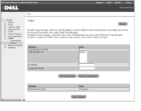
On the Traps page, you can specify management stations that receive authentication failure messages and other trap messages from the switch.
|
NOTICE: The switch does not prevent IP addresses that are not in the Trap Manager list from accessing the switch through SNMP. You only need a valid community string for access. |
The following options are available:
To add a trap manager, type the new IP address in the IP Address box, type the appropriate SNMP community in the Community String box, and then click Add Trap Manager. To delete a trap manager, click the entry in the Trap Manager List, and then click Remove Trap Manager.
The following table summarizes the equivalent CLI commands for items in the SNMP/Traps page.
Console(config)#snmp-server host 10.1.19.23
Console(config)#snmp-server enable traps link-up-down
Console(config)#
Multicasting is used to support real-time programs such as video conferencing or streaming audio. A multicast server does not have to establish a separate connection with each client. Instead, it broadcasts its service to the network and to any hosts that are supposed to receive the multicast register with their local multicast routers/switches. This approach reduces the network overhead required by a multicast server. However, each time the broadcast traffic passes through a multicast router/switch, the traffic must be carefully queried to ensure that only hosts that subscribe to the service receive the broadcast.
The switch uses the Internet Group Management Protocol (IGMP) to determine if any attached hosts are supposed to receive a specific IP multicast service. IGMP runs between hosts and their adjacent multicast routers/switches. IGMP is a multicast host registration protocol that allows any host to inform its local router that the host is supposed to receive transmissions addressed to a specific multicast group.
IGMP requires one device to act as the querier on each LAN subnetwork. The querier is the IGMP-enabled device that periodically sends query messages to all hosts asking them if they want to receive multicast traffic. Hosts respond with report messages, indicating to multicast groups that they wish to join or to which group they already belong. The querier then propagates the service requests on to any adjacent multicast switch/router to ensure that it continues to receive the multicast services.
IGMP-enabled devices prune multicast traffic on the network by passively snooping on IGMP report messages passing through their ports. The devices monitor host report messages, pick out the multicast group registration information, and then configure filters accordingly so that multicast traffic for particular groups is not forwarded on to ports that do not require it. This capability significantly reduces the multicast traffic on the network.
The Multicast Support page contains links to the following pages:
With IGMP Snooping, you can configure the switch to forward multicast traffic intelligently. Based on the IGMP query and report messages, the switch forwards traffic only to the ports that request multicast traffic. This querying prevents the switch from broadcasting the traffic to all ports and possibly disrupting network performance.
|
NOTE: IGMP requires a router that learns about the presence of multicast groups on its subnets and keeps track of group membership. |
On the IGMP Setting page, the following options are available:
To save any changes you make in this page, click Apply Changes. If you don't want to save the changes, click Refresh.

The following table summarizes the equivalent CLI commands for items in the Multicast Support/IGMP Setting page.
Console(config)#ip igmp snooping
Console(config)#ip igmp snooping querier
Console(config)#ip igmp snooping query-count 10
Console(config)#ip igmp snooping query-interval 100
Console(config)#ip igmp snooping query-max-response- time 20
Console(config)#ip igmp snooping query-time-out 300
Console(config)#ip igmp snooping version 1
Console(config)#exit
Console#show ip igmp snooping
Service status: Enabled
Querier status: Enabled
Query count: 10
Query interval: 100 sec
Query max response time: 20 sec
Query time-out: 300 sec
IGMP snooping version: Version 1
Console#
You can use the IGMP Member Port Table page to assign ports that are attached to hosts that are supposed to receive a specific multicast service.
The following options are available:
|
NOTICE: You must set at least one port or trunk as a static member before you add a new multicast IP address. If you remove all static members from a group, the IP address is also removed. |
To save any changes you make in this page, click Apply Changes. If you don't want to save the changes, click Refresh.

The following tables summarize the equivalent CLI commands for items in the Multicast Support/IGMP Member Port Table page.
Console(config)#ip igmp snooping vlan 1 static 224.1.2.3 ethernet 1/11
Console(config)#exit
Console#show bridge 1 multicast
VLAN M'cast IP addr. Member ports Type
---- --------------- ------------ -------
1 224.1.2.3 Eth 1/11 User
Console#
You can use the Multicast Router Port Settings page to display or set ports on the switch that are attached to a neighboring multicast router/switch for each VLAN ID.
The following options are available:
To save any changes you make in this page, click Apply Changes. If you don't want to save the changes, click Refresh.

The following table summarizes the equivalent CLI commands for items in the Multicast Support/Multicast Router Port Settings page.
Console(config)#ip igmp snooping vlan 1 mrouter ethernet 1/5
Console(config)#exit
Console#show ip igmp snooping mrouter vlan 1
VLAN M'cast Router Port Type
---- ------------------ -------
1 Eth 1/ 5 Static
Console#
From the Statistics page, you can chart a variety of system data. You can see the value of each bar or line in the chart by clicking the bar. For each chart, after you have set all the variables, click Draw.
|
NOTE: Rates are displayed as counts per second. Counters are cumulative from the last time the system was booted. |
The Statistics page contains links to the following pages:
The Chart page compares one type of statistic across all ports or trunks. You must define the following variables:

The Table page lists, in table format, all statistics counters for a specific port or trunk. You must specify the port or trunk from the drop-down menus, and then click Query.

The following table summarizes the equivalent CLI commands for items in the Statistics/Table page.
|
Command |
Usage |
|---|---|
show interfaces counters interface | Statically configures a multicast router port |
clear counters interface | Clears statistics on an interface |
|
NOTE: Clearing counters are only available in the CLI. |
Console#show interfaces counters ethernet 1/17
Ethernet 1/17
Iftable stats:
Octets input: 91248, Octets output: 343887
Unitcast input: 680, Unitcast output: 593
Discard input: 0, Discard output: 0
Error input: 0, Error output: 0
Unknown protos input: 0, QLen output: 0
Extended iftable stats:
Multi-cast input: 0, Multi-cast output: 1854
Broadcast input: 138, Broadcast output: 165
Ether-like stats:
Alignment errors: 0, FCS errors: 0
Single Collision frames: 0, Multiple collision frames: 0
SQE Test errors: 0, Deferred transmissions: 0
Late collisions: 0, Excessive collisions: 0
Internal mac transmit errors: 0, Internal mac receive errors: 0
Frame too longs: 0, Carrier sense errors: 0
RMON stats:
Drop events: 0, Octets: 435135, Packets: 3430
Broadcast pkts: 303, Multi-cast pkts: 1854
Undersize pkts: 0, Oversize pkts: 0
Fragments: 0, Jabbers: 0
CRC align errors: 0, Collisions: 997976404
Packet size <= 64 octets: 2584, Packet size 65 to 127 octets: 211
Packet size 128 to 255 octets: 198, Packet size 256 to 511 octets: 317
Packet size 512 to 1023 octets: 95, Packet size 1024 to 1518 octets: 25
Console#
Console#configure
Console(config)#clear counters ethernet 1/17
