 VLANs and Frame Tagging
Dell™ PowerConnect™ 5224 Systems User's Guide
The PowerConnect 5224 switch supports IEEE 802.1Q-compliant virtual LANs (VLANs). This capability provides a highly efficient architecture for establishing VLANs within a network and for controlling broadcast/ multicast traffic between workgroups. Central to this capability is an explicit frame tagging approach for carrying VLAN information between interconnected network devices.
With frame tagging, a four-byte data tag field is attached to frames that cross the network. The tag identifies to which VLAN the frame belongs. The tag may be added to the frame by the end station itself or by a network device, such as a switch. In addition to VLAN information, the relative priority of the frame in the network can be specified by the tag.
VLANs provide greater network efficiency by reducing broadcast traffic, and they also allow you to make network changes without having to update IP addresses or IP subnets. VLANs inherently provide a high level of network security, since traffic must pass through a Layer 3 switch or a router to reach a different VLAN.
The PowerConnect 5224 switch supports the following VLAN features:
By default, VLAN operation on the switch is enabled. Therefore, all frames are transferred internally through the switch with a VLAN tag. This tag may already be on the frame entering the switch, or added to the frame by the switch. VLAN information already existing on frames entering the switch is automatically handled by the switch. The switch learns VLAN information from tagged frames and appropriately switches frames out the proper ports based on this information. The configuration of VLANs for frames entering the switch without tags must be made by the user of the switch. This configuration can be made either through the web or console interface, or through Simple Network Management Protocol (SNMP).
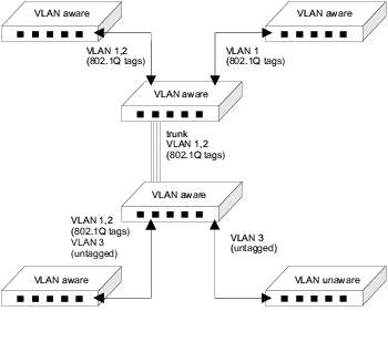
Before enabling VLANs for the switch, you must first assign each port to the VLAN groups in which it will participate. By default, all ports are assigned to VLAN 1 as untagged ports. You should add a tagged port (a port attached to a VLAN-aware device) if you want it to carry traffic for one or more VLANs and the device at the other end of the link also supports VLANs. Assign the port at the other end of the link to the same VLANs. However, if you want a port on this switch to participate in one or more VLANs and the device at the other end of the link does not support VLANs, you must add an untagged port (a port attached to a VLAN-unaware device).
Port-based VLANs are tied to specific ports. The switch's forwarding determination is based on the destination MAC address and its associated port. Therefore, to make valid forwarding and flooding decisions, the switch learns the relationship of the MAC address to its related port (and to the VLAN) at run-time.
Packets that the switch receives are treated in the following ways:
 |
NOTE: You can change port VLAN membership settings in the VLAN Membership page. |
Port overlapping can be used to allow access to commonly shared network resources among different VLAN groups, such as file servers or printers. If you implement VLANs that do not overlap but still need to communicate, you must connect them using a router or Layer 3 switch.
Ports can be assigned to multiple tagged or untagged VLANs. Each port on the switch is, therefore, capable of passing tagged or untagged frames. To forward a frame from a VLAN-aware device to a VLAN-unaware device, the switch first determines where to forward the frame. The switch then strips off the VLAN tag. However, to forward a frame from a VLAN-unaware device to a VLAN-aware device, the switch first determines where to forward the frame. It then inserts a VLAN tag reflecting this port's default VID. The default port VLAN ID is 1, but it can be changed from the VLAN Port Settings page.
GARP VLAN Registration Protocol (GVRP) defines a way for switches to exchange VLAN information to automatically register VLAN members on ports across the network.
GVRP uses GVRP Bridge Protocol Data Units (GVRP BPDUs) to advertise static VLANs to other switches in the network. Any GVRP-enabled device receiving the advertisements can dynamically join the advertised VLAN. All GVRP-dynamically learned VLANs operate as tagged VLANs. A GVRP-enabled port only joins a VLAN when an advertisement for that VLAN is received on that specific port. A GVRP-enabled port forwards advertisements from other ports on the switch but does not join the advertised VLAN.
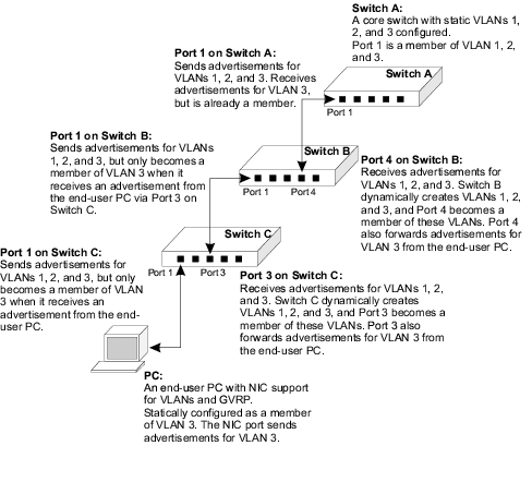
Hosts, such as computers and servers, can be connected to switch ports that are part of a statically configured VLAN. If GVRP is enabled on the switch, these VLANs are advertised to the rest of the network. If a host (or its network adapter) supports GVRP, it can directly indicate the VLAN groups that it is supposed to join. When the attached GVRP-enabled switch receives the VLAN advertisements, it automatically places the receiving port in the specified VLANs and then forwards the advertisements to all other ports. When the advertisements arrive at another GVRP-enabled switch, the switch places the receiving port in the specified VLANs, and passes the advertisements on to all other ports. As a result, VLAN requirements are spread throughout the network, which allows GVRP-compliant devices to be automatically configured for VLAN groups based solely on host requests.
The following figure shows how GVRP can propagate VLANs across a network.
The following four examples demonstrate typical web-interface VLAN configurations for the switch.
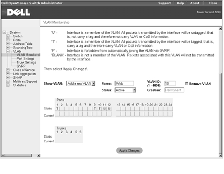
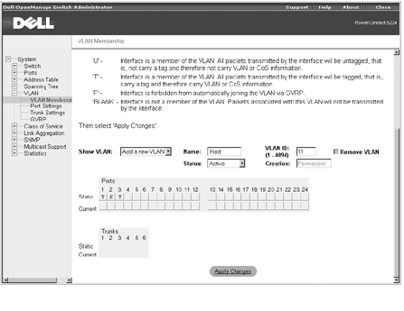
Example 1 illustrates a simple two-group VLAN setup.
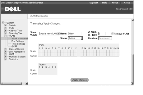
Because there are no ports in the new VLAN, all the port and trunk toggle buttons are blank.
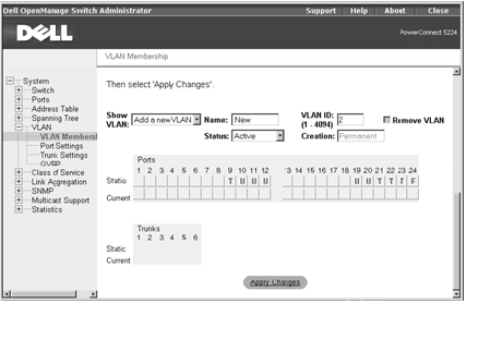
Example 2 illustrates a more complicated setup and demonstrates several scenarios for configuring VLANs.
All switch ports remain as members of the default VLAN (VLAN
ID 1).
|
VLAN ID |
Name |
Port Members (Tagged/Untagged) |
|---|---|---|
2 | Admin | 1 (U), 2 (U), 10 (U) |
5 | Internal | 1 (U), 4 (U), 5 (U) |
10 | Web | 1 (T), 9 (T), 10 (T), 11 (U), 12 (U) |
15 | Collocation | 1 (U), 2 (U), 14 (U) |
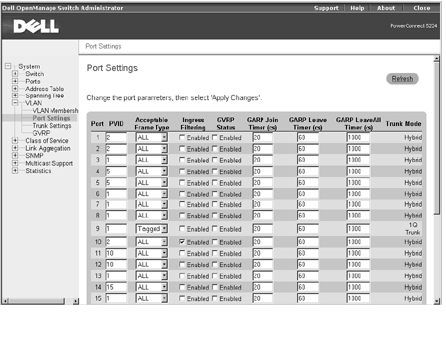
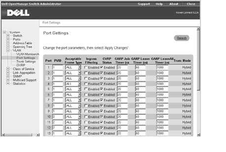
The specific ports shown in the previous figure have the following PVID settings. The PVID settings for each port are configured in the Port Settings page.
Port 01: 2 | Port 05: 5 | Port 09: 1 | Port 13: 1 |
Port 02: 2 | Port 06: 1 | Port 10: 2 | Port 14: 15 |
Port 03: 1 | Port 07: 1 | Port 11: 10 | Port 15: 1 |
Port 04: 5 | Port 08: 1 | Port 12: 10 | Port 16: 1 |
The PVID of a port must be set to a VLAN ID of which the port is an untagged member.
|
NOTE: Port 9 cannot be removed from VLAN 1 because its PVID is set to VLAN 1. |
The VLANs set up in the this example procedure produce the following results:
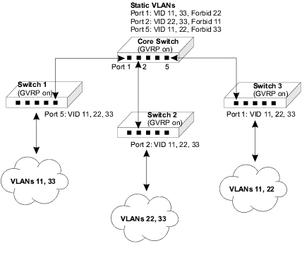
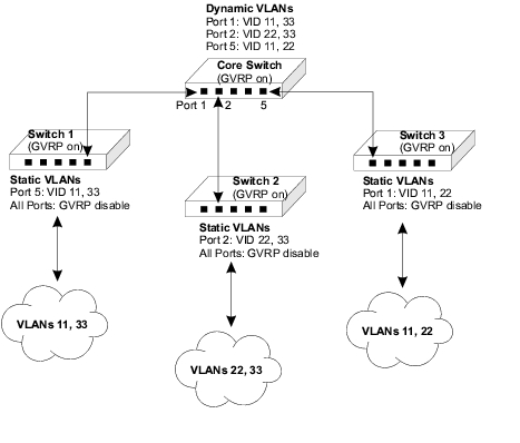
Example 3 illustrates how GVRP is implemented where VLANs configured in a core aggregation switch are automatically learned by wiring-closet switches.
|
VLAN ID |
Name |
Port Members (Tagged/Forbidden) |
|---|---|---|
11 | Red | 1 (T), 3 (T), 2 (F) |
22 | Green | 2 (T), 3 (T), 1 (F) |
33 | Blue | 1 (T), 2 (T), 3 (F) |
With GVRP enabled on the core switch, GVRP advertisements for the three static VLANs are sent from all ports on the switch. When the three wiring-closet switches receive the advertisements, they dynamically create the VLANs and the receiving ports join these VLANs.
The clouds connected to the wiring closet switches in the previous figure represent other switches and end-users on that network segment. By setting one VLAN as forbidden on the connecting port, the core switch limits each network segment to only two of the VLANs. For example, users attached to Switch 3 have access to VLANs 11 and 22, but not to VLAN 33. End-user requests enable ports on Switch 3 to join VLAN 33, but these users do not have access to the rest of the network.
Example 4 illustrates how GVRP is implemented where VLANs configured in wiring-closet switches are automatically recognized by a core aggregation switch.
|
VLAN ID |
Name |
Port Members (Tagged/Untagged) |
|---|---|---|
11 | Red | 5 (T), (other ports as required) |
33 | Blue | 5 (T), (other ports as required) |
|
VLAN ID |
Name |
Port Members (Tagged/Untagged) |
|---|---|---|
22 | Green | 2 (T), (other ports as required) |
33 | Blue | 2 (T), (other ports as required) |
|
VLAN ID |
Name |
Port Members (Tagged/Untagged) |
|---|---|---|
11 | Red | 1 (T), (other ports as required) |
22 | Green | 1 (T), (other ports as required) |
With GVRP enabled on the wiring closet switches, GVRP advertisements for the configured static VLANs are sent to the core switch. When the core switch receives the advertisements, it dynamically creates the VLANs and places the receiving ports in these VLANs.
The GVRP port settings on the wiring-closet switches need to be set to disabled. This setting prevents these switches from dynamically creating other VLANs, or adding port members to the existing static VLANs. The global GVRP switch setting still enables the static VLANs to be advertised to the rest of the network. For example, users attached to Switch 3 have access to VLANs 11 and 22, but not to VLAN 33. VLAN 33 cannot be created on Switch 3, even though advertisements are received on Port 1 from other switches in the network.