mdl2smv: A tool for Translating Automotive Feature Models in Matlab's Stateflow to SMV
The main goal of my work is to be able to verify the absence of feature interactions in the integration of automotive features and the lack of errors in their design. After identifying the unique characteristics of the automotive domain, we have recognized that symbolic model checking is an appropriate technique to detect feature interactions between automotive feature designs. We selected the model checker SMV because of its powerful features for model checking and flexible input language, in which we can describe the semantics of Stateflow and of the composition of features. Matlab's Stateflow language is used extensively for designing the controllers of embedded components in the automotive and avionics industry.
We have created mdl2smv, a tool for translating a subset of the Stateflow language into the notation of Cadence SMV. This page describes how the elements of Stateflow are mapped into elements of SMV, as well as the design decisions we made in the creation of our translator. We also explain the supported Stateflow elements, the limitations of our tool and semantics issues addressed during the translation process. This information can also be found in our paper Translating Models of Automotive Features in MATLAB’s Stateflow to SMV to Detect Feature Interactions [2] . This page also contains implementation details about the mdl2smv package, as well as explanation for generating and running the executable.
Overview
For automotive embedded systems, models that describe the functionality of features are often created using Matlab's Stateflow. Simulink is software for modelling, simulating, and analyzing dynamic systems, and Stateflow is an interactive graphical design tool that works with Simulink to model and simulate event-driven systems. Stateflow models are included in a Simulink model by placing them in Stateflow blocks, so they can be simulated. There is no formal semantics of Stateflow, and therefore, its behaviour is defined during simulation. The syntax of Stateflow is similar to that of Statecharts, but they differ in semantics.
Simulink/Stateflow stores the information about a model in an ASCII file with a .mdl extension. We extract the necessary information from the .mdl file and directly translate it to the SMV modelling notation because its notation can reflect precisely the semantics of the design models in Stateflow, and that of the composition of features.
Our tool could potentially have been implemented as an addition, or plug-in, to the Simulink/Stateflow interface instead of as stand-alone program. The primary benefit of a stand-alone implementation is that it is more portable because a Matlab license is not necessary. Also, there is no need for additional interface development since we simply make use of an executable program, which takes one text file as input and gives another text file as output. The translator is written in C, having as input an ASCII .mdl file and as output an ASCII .smv file. We use a multi-pass translation approach because of the way the information is organized in the .mdl file. Thus, we gather the information and process it to generate the Stateflow semantics in SMV, e.g., transitions are listed in order (given their priority of execution), and AND-states follow sequential execution (different from Statecharts semantics).
The files that are part of the package to create the mdl2smv executable tool are: (For questions, please e-mail Alma Juarez):
- mdlparser.l: Token definitions to capture the Stateflow portion of the .mdl file and ignore the rest.
- mdlparser.y: Grammar definitions given the structure of the .mdl file.
- data.h: Definition of constants for console display used during debugging.
- structs.h: Declaration of function prototypes and of the generic node structure to hold the information required for all Stateflow entries.
- functions.c: C functions for the creation of nodes, and the addition of attributes to the respective list. Some functions for string manipulation are also included.
- printing.c: C functions for the SMV output creation.
- main.c: Calls for parsing routines and SMV creation functions.
- Makefile: Makefile for for the generation of mdl2smv executable, using flex/bison
Once the executable is generated with the Makefile, type the following command at the prompt to obtain the translated SMV model:
./mdl2smv input_file_name.mdl OPTION > output_file_name.smv
where OPTION equal to "-t" indicates mdl2smv to create several transition variable declarations, and if the option is not included, it generates only one transition variable declaration (the default).
Even though the name of a transition is not explicit in the graphical view of the model, which is the default view, the information about the name of each transition is part of the .mdl textual description of the Stateflow model. Stateflow uses the name of the transition, which is simply a number, while reporting syntactic errors found during parsing or simulation. We have found this information very useful, and to record and report concisely the transitions taken in a path, and therefore, include it as part of the translated models to be reported as part of our analysis. The name of a transition variable is prefixed by "Tr", whereas the number that identifies a transition is prefixed with "t" to denote that the identifier refers to a transition. For some applications and analyses, it is sufficient to learn what was the last transition taken, which would be reported by default when no option is provided. However, whenever AND-states are present, several transition variables are necessary to report the transitions taken. Because of the sequential execution of AND-states, a model in Stateflow responds to an input in several steps, i.e., as a big-step, that is, a sequence of transitions within the components of the feature (as explained in more detail in Semantics Issues ). This is the reason why the option "-t" is included.
Next, we explain syntax and semantics details related to the tool and translation, followed by more information on the translation process.
Supported Stateflow Elements and Input Model Assumptions
The subset of Stateflow that we currently support are:
- ‘Exclusive’ / ‘OR-states’
- ‘parallel’ / ‘AND-states’
- Input events ports
- Input and output data ports
- Transition actions
- History states
In our translator, we assume that Stateflow design models adhere to the following syntax rules:
- The designer should specify the type of data used for all input data, output data, local data, etc. To do so, in the Stateflow Model Explorer, click on the data variable. Then, set “Data type mode:” to “Built-in” and set “Data type:” to appropriate type (double, boolean, etc.).
- The designer should also specify the ranges of data values when appropriate (e.g., when using doubles). To do so, in the Stateflow Model Explorer, click on the data variable. Then, select “Value attributes” and enter the "Minimum value" and "Maximum value".
- Quotes should not be part of the string of any label.
- Only numbers, letters, or an underscore should be included in names.
- Spaces should not be included in data names.
- Ensure that actions written in transitions have the form “ x = y ; ”.
- Ensure that no two Stateflow models have the same name for their Simulink block name (i.e., “Chart”, which is the default), and provide a meaningful name.
- When using our translator, if a parsing error occur, designer should ensure that all label strings are on a single line. (Parsing errors might occur due to newline characters \n and \r).
- Outputs that are meant to be commands (e.g., request to actuators) need to follow the naming convention set_ACT, where ACT is the name of the device where the command is going to be executed (e.g., brakes).
Semantics Issues
In Stateflow, at each level of the hierarchy, only one kind of decomposition can be chosen, i.e., all states at the same hierarchy level must be either OR-states or AND-states, which must be preserved in the generated models.
Each transition has also a priority of execution, determined by the hierarchy level of the transition’s destination state, the type of information in its label (e.g., events have priority over conditions) and the geometric position of the transition source.
One of the semantics issues we had to solve is that AND-states in Stateflow do not run concurrently (unlike AND-states in Statecharts). Each AND-state is executed sequentially following its respective execution order. The execution order is based on the geometric position of the AND-states, where priority is assigned from top to bottom and then from left to right, according to the rules:
- The higher an AND-state’s vertical position in the diagram, the higher its priority for execution.
- Among AND-states with the same vertical position, the left-most state receives highest priority.
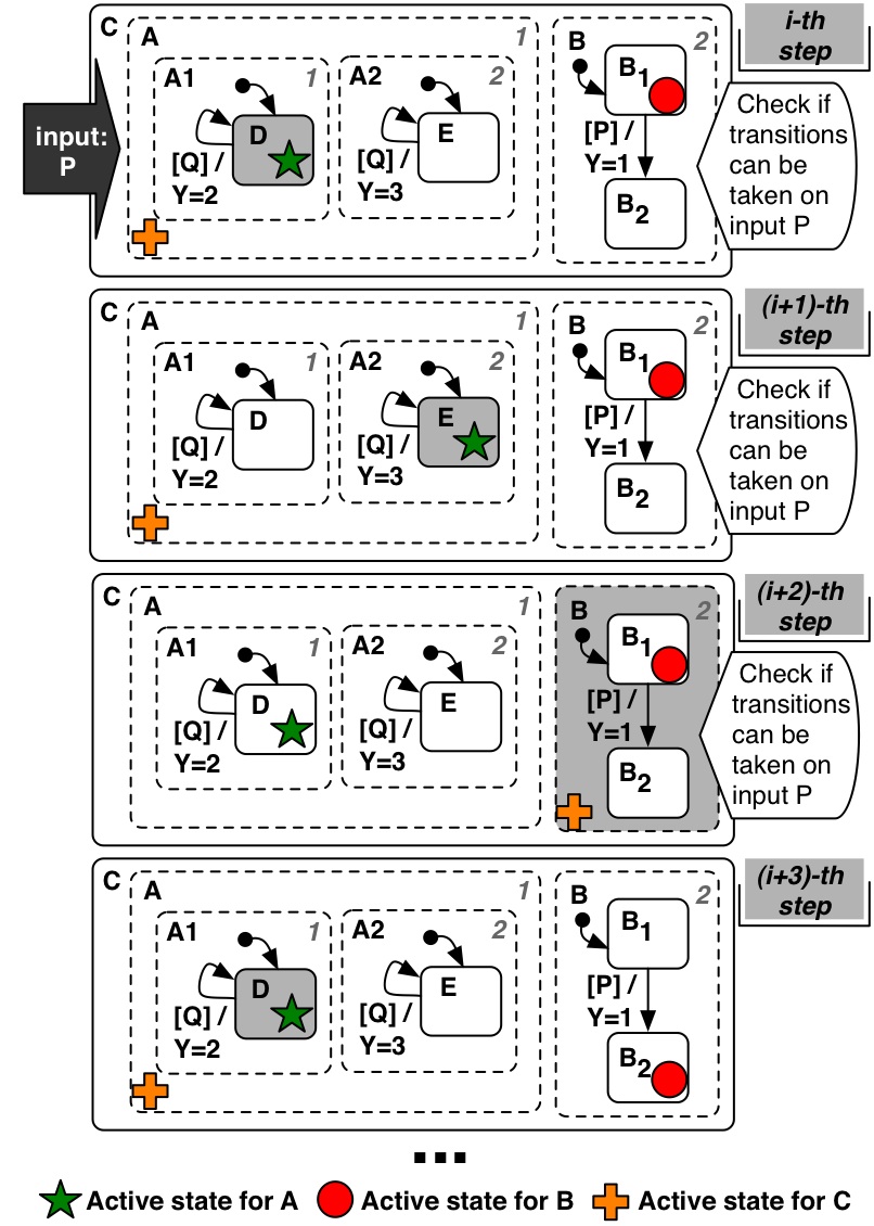
The lower the number, the higher the priority. This order determines when each AND-state performs the actions it executes, only one state at a time for a given set of inputs, but the same set of inputs is used for all AND-states in the same level of the hierarchy. To translate the behaviour of AND-states in Stateflow, we had to ensure (1) that AND-states execute sequentially in the order assigned to the components because Stateflow models are single-threaded, and (2) that all AND-states in the same hierarchy use the same set of inputs when checking which transitions can be taken. The following example from our paper Modelling Feature Interactions in the Automotive Domain [1] illustrates the Stateflow execution of AND-states, which consist of a sequence of transitions taken in different siblings of an AND-state while all siblings react to the same set of inputs.
Another semantic issue is that when several features are integrated in a vehicle, they work concurrently, i.e., they all receive the same input (or set of inputs) simultaneously. However, even though all features receive their inputs synchronously, each feature must preserve its individual Stateflow semantics, e.g., AND-states execute their components sequentially. Also, when a feature model with ordered composition is combined with a feature model with fewer or no ordered composition operators, the later model must idle maintaining the values of its outputs. More details on these issues, and our proposed solution for the modelling and translation, can be found in Modelling of Automotive Features and Definition of Feature Interaction in the Automotive Domain [1] .
Parsing
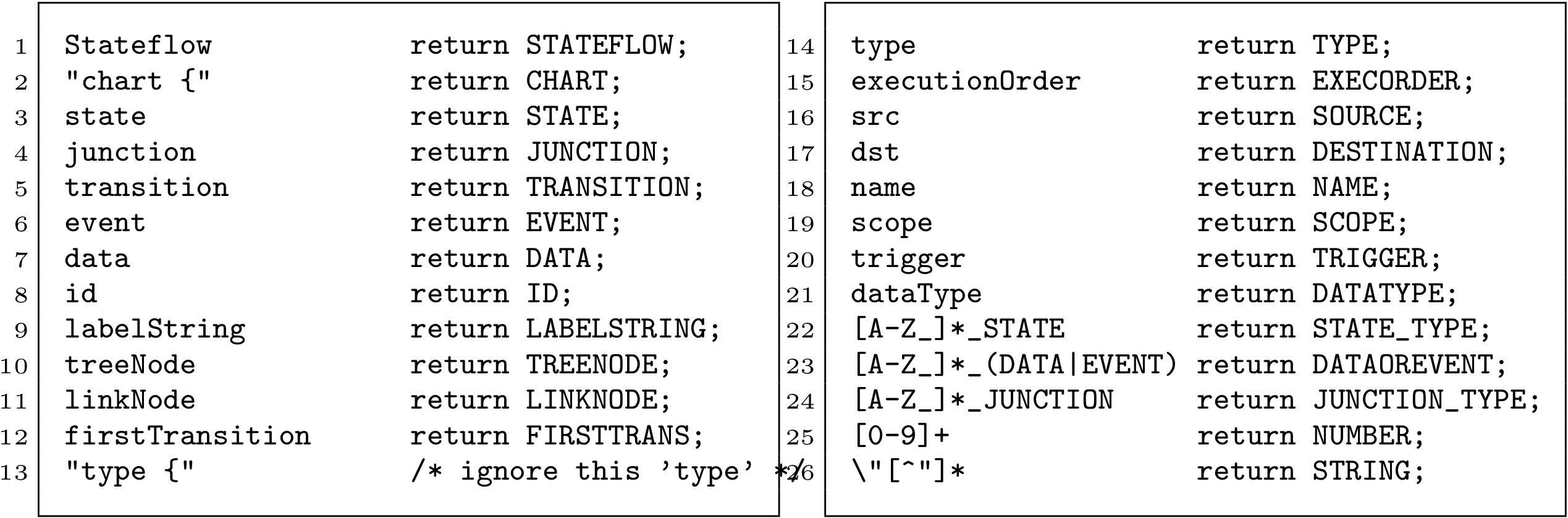
Our lexical analyzer was written in Flex, the GNU version of Lex. Using the structure of the .mdl file, the token definitions capture the important objects, as well as their attributes and values found in the Stateflow portion of the .mdl file and ignore the rest. The Stateflow objects captured are states, transitions, junctions, events, and data. These objects generally include as attributes: ID, label, node relationship (for tree structure) and type-specific information such as the source state of a transition, or the data-type. The file containing the lexical definitions is called mdlparser.l, and the following figure shows the main tokens defined using regular expressions.
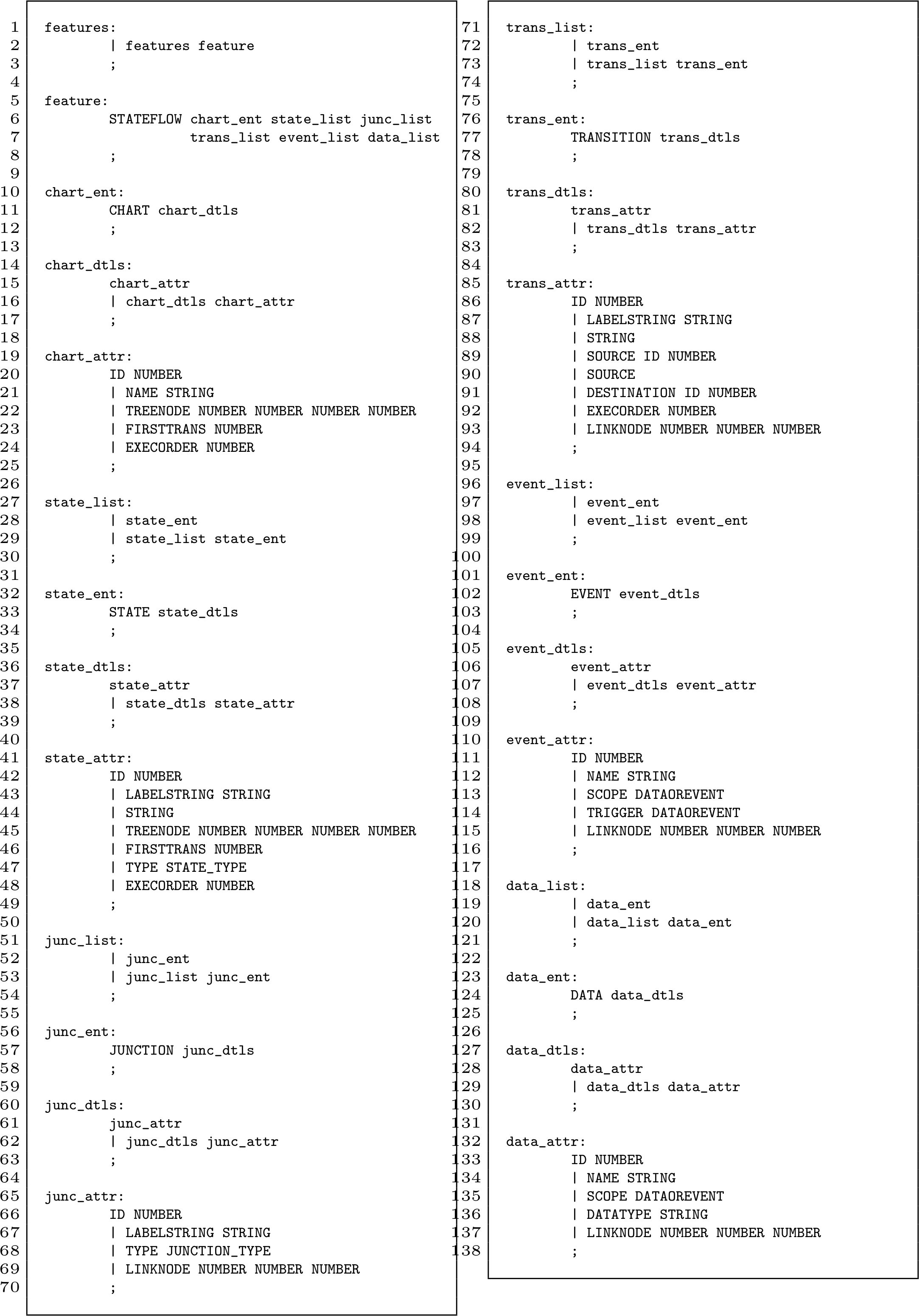
The lexical analyzer is directly synchronized with the GNU parser generator Bison. The parser generator takes the tokens defined in the lexer and breaks down the input recursively to create the abstract syntax tree. Our translator calls C functions to create a tree for the states, following the internal organization of states in Stateflow, and it also creates a series of linked lists for each of the Stateflow objects, which contain all the necessary information about the model. The file containing the grammar is called mdlparser.y, and the following figure shows the grammar definitions without the function calls that create the parse tree.
Translation Functions in C
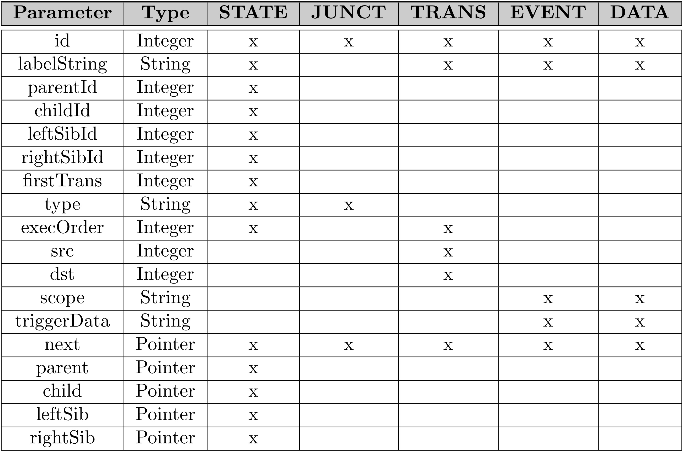
Our code is based on the series of nodes stored in memory as linked lists and a tree. We defined in structs.h a generic node structure to hold any necessary information required for all Stateflow entries. This simplifies our translation process by having generic functions for creating and traversing, instead of having to write different functions for creating and traversing each kind of Stateflow object. For each Stateflow entry found in the .mdl file, a node is created and stored in one of five linked lists, depending on its kind, having one link list for each of the kinds of Stateflow entries: states, junctions, transitions, events and data. We also created a tree structure from information found in the .mdl file to have easy access to the same internal representation that Stateflow uses to organize states. The C functions for the creation of nodes, and the addition of attributes to the respective list, are included in functions.c. The following table shows the parameters stored in a node and which Stateflow entry requires them.
Once all the Stateflow entries are stored in memory, we proceed to the creation of the SMV file, which preserves the semantics of Stateflow. Each Stateflow design model becomes a separate module for SMV, i.e., we create one SMV module per feature design model in Stateflow. The following C functions, contained in the printing.c file, produce the SMV output:
- printSMV - Main printing function call. It prints the name of the module,
the module parameters (all the inputs and outputs used), and calls the functions
to create the rest of the SMV output (printInputOutput, printStates, printInits, and
printSwitch).
- printInputOutput - Function that prints the module’s variable declarations
(inputs, outputs and local) and their values as enumerations, ranges, or Booleans, depending
on their type in Stateflow. Events are defined with an enumerated type variable containing
the names of the events part of the Stateflow model.
- printStates - Function that prints the declaration of the states that are
part of the module. A variable is declared per level of state hierarchy, having enumerated
all possible states at the state hierarchy level (for OR- and AND-states). The possible value of
each superstate are the names of its substates.
- printInits - Function that makes use of the default transition information
stored in the .mdl file to initialize, using the init operator, to define the first active state
at each level of the hierarchy. If AND-states are encountered, there is no default transition
and the state with execution order of 1 is used for initialization.
- printSwitch - Function that prints the state transitions, which is the
most complex process of the translation since we have to account for different semantic
components (e.g, sequential execution of AND-states). This function is called
recursively, having as its only argument the pointer
to the state node that is considered as the source of transitions.
- Variable Declarations: Stateflow variables are declared as SMV variables of the appropriate type. Events are declared as an enumerated type variable containing the names of the possible events. Variables (inputs, outputs and local) are declared as enumerations, ranges, or Booleans in SMV. Stateflow output to actuators from automotive features are really parameterized commands, which taken in isolation from a model of the dynamics of a car, are not variables that should maintain their values over time. In SMV, we represent parameterized events by (1) a variable that has the value associated with the command and (2) a boolean that represents the presence or absence of the command. To distinguish output request to actuators from other kind of outputs (e.g., HVI, Warning), so we use the naming convention set_ACT, where ACT is the name of the device where the command is going to be executed. The associated boolean variable is created by the translator as a local, and it is named ACT_req.
- State Stateflow states are declared as SMV variables of enumerated type. Declaration of one state variable per level of state hierarchy in the Stateflow model. The possible value of each superstate are the names of its substates. Use of the default transition information and the SMV init operator to define the first active state at each level.
- Transitions are modelled in SMV using switch statements. Nested switch statements follow the hierarchy of states in the Stateflow model and check whether the model is in the source state of a transition. Within the switch statement, there is a case for each state at the corresponding level of the hierarchy. Within each case statement, there is a series of if-then-else statements, one per transition, checking whether the event and/or condition of the transition are satisfied. The order of the if-then-else statements corresponds to the transitions’ priority of execution. If we are creating transitions within a nested switch statement (i.e., at a hierarchy level other than one), outgoing transitions from the superstate are listed before inner transitions, in order to follow their priority of execution. Then, internal transitions are listed; first, the transition with highest priority, and consecutively creating the rest in decreasing priority.
- Within each if statement, there is an assignment for every output variable. For variables that are directly changed by the transition, the assignment corresponds to the actions of the transition of the Stateflow design model. For any output variable whose value is not explicitly defined in the transition of the Stateflow model, we assign it the value it currently holds. Also, within the if statement, there is an assignment for the next state as a result of the transition. For OR-states, the assignment corresponds to the state name that is the destination of the transition (possibly following default states for destinations that are superstates). For AND-states, the state assignment correspond to the state name that is next in execution order, following any level in the hierarchy, which makes the printing process with AND-states intricate.
- AND-states To model the sequential execution of AND-states in SMV: (1) We set the next state value for an AND-state to the next component of the AND-state or to the component with execution order 1 if in the last component. (2) We maintain all inputs values until the step where control returns to the first component of the AND-state then allow the inputs to change non-deterministically in this step (use of SMV macros "stable" and "sys_stable").
- Feature composition To model the concurrent execution in SMV: (1) We check when all features are ready to begin with new inputs (use SMV macros "stable" and "sys_stable"). (2) We check for feature interactions when the macro is true since at this point all the features have produced their outputs for a set of inputs.
- The approach with macros does not introduce any extra steps in the computation.
NOTE (For debugging purposes): The most important constant definitions for console display used during debugging, and declared in data.h, are:
- The constant TREEDEBUG, when uncommented, creates contents of file "tree.txt" (called in makeTree())
- The constant TRANSDEBUG, when uncommented, creates contents of file nodes.txt (called in linkTrans())
- The constant PRINTLIST, when uncommented, creates contents of file lists.txt (called in main)
Limitations
The subset of Stateflow not normally used in the creation of automotive design models, thus not supported by our tool, is:
- Condition actions in transitions
- Actions within states
- Connective junctions
- Graphical functions / MATLAB functions
- Temporal conditions (use of temporal logic within Stateflow)
- Event broadcasting
If these syntactic elements are desired while designing a feature model, in most cases, an equivalent design can be created without these syntactic elements.
References
- A. L. Juarez-Dominguez, N. A. Day, and J. J. Joyce, “Modelling Feature Interactions in the Automotive Domain,” in Proc. of the 2008 International Workshop on Modeling in Software Engineering (MiSE ’08), pp. 45–50, ACM Press, 2008.
- A. L. Juarez-Dominguez, N. A. Day, and R. T. Fanson, “Translating Models of Automotive Features in MATLAB’s Stateflow to SMV to Detect Feature Interactions,” in Proc. of the 26th International Systems Safety Conference, System Safety Society, 2008.