 ERA/MC Controller Features
Dell™ Embedded Remote Access/MC User's Guide
System and Operating System Support
Configuring and Using the Controller
Supported Remote Access Connections
Event Notification Through Remote Access Ports
Remote Access Security Features
Obtaining Technical Assistance
The Dell™ Embedded Remote Access/MC (ERA/MC) controller, is a systems management hardware and software solution designed to provide remote management capabilities for the server modules and shared resources in your Dell PowerEdge™ 1655MC system.
The system can include up to six server modules. To function as a system, a server module is inserted into a chassis which includes power supplies, fans, a system management module, and at least one network switch module. The power supplies, fans, system management module, and network switch module(s) are shared resources of the server modules in the chassis.
The ERA/MC controller consists of firmware embedded on the systems management card in the system chassis. The controller provides interfaces that enable you to remotely manage and monitor the server modules and shared resources of the system through the network or management serial connection.
 |
NOTE: The system in which the controller is embedded is referred to as the managed system. A remote system that accesses the controller is referred to as a management station. |
The ERA/MC controller offers a complete hardware and software solution that allows you to remotely access an inoperable system so you can get the system up and running as quickly as possible. The controller also provides alert notification when the system is down, logs the probable cause of system crashes related to the controller or shared chassis components, and allows you to remotely restart the system.
The controller uses a proprietary bus, has its own microprocessor and memory, and is powered by the system power supplies. The controller remains powered as long as an AC connection is present and regardless of whether the power supplies are on or off.
The controller provides alerts if a problem is detected and can possibly prevent a system crash. By communicating with the system's ESM, the controller reports warnings or errors related to voltages, temperatures, fan speeds, and power supplies.
The controller offers the following features:
|
NOTE: For more information about setting up and configuring your system in a network, see your System Configuration Guide. |
If the managed system goes down or becomes unresponsive, or if you want to monitor sensor status while the system is running, you can access the controller's Web-based remote access interface, serial command shell interface, or remote racadm utility to perform crash recovery actions or to obtain system information.
Logs enable you to view events as they occur on the system, including actions and alerts issued by the controller.
IPMI 1.0 defines common interfaces to the hardware that is used to monitor your system's physical health characteristics, such as temperature, voltage, fans, power supplies and chassis. These monitoring abilities provide information that enables system management, recovery and asset tracking.
Your controller supports the PowerEdge 1655MC system and the following software.
|
NOTE: See your racread.txt file for updated system support information. |
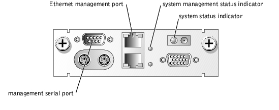
The controller's embedded circuit and firmware is contained on the systems management module. This module provides serial and Ethernet management ports and a system management status indicator (see Figure 1-1). For more information about the system, the system management module, or the server module features and indicators, see your system User's Guide.
Figure 1-1. System Management Module Features
Your controller comes with software components that provide a set of services for each supported operating system. The services interface with the controller hardware to allow the following functions:
The following three interfaces work together to allow you to access, configure, and use the controller:
 |
NOTICE: It is recommended that you do not connect the ERA/MC management port to the same subnet as switch 1; this action may cause a bridge loop. |
It is recommended that you use the serial command shell for the initial configuration of the controller. After the initial configuration, you may use the Web-based remote access interface, serial command shell, or remote racadm utility to further configure and use your controller. You may issue commands through either the management serial port or through the Ethernet management port. For more information, see "Configuring Your Controller."
|
NOTE: You can also issue commands through switch 1 on your system. For information about using the switch, see the switch documentation that came with your system. |
An important feature of the controller is its ability to notify you when a system fails. To do this, the controller sends an alert using one or more of its remote access port connections. The controller can send two types of alerts: e-mail and SNMP traps.
Because the controller firmware has an embedded Web server, you can connect to the controller from a management station and view the status of events that occur in the managed system without installing any software on the management station other than a supported Web browser and the racadm command-line utility software.
After receiving an alert, you can view the event log to determine the nature of the problem. The Web browser connects to the controller using the 10- or 100-Mbps Ethernet management port on a LAN/WAN.
To recover a server module from a system crash, you can perform a remote (hard) reset or power cycle and view the boot process through the controller Web-based remote access interface.
The controller firmware constantly monitors the IPMI hardware log to determine when to generate an e-mail or SNMP trap event to a specified user.
|
NOTE: E-mail events are sent to a specified e-mail address on an SMTP server. SNMP trap events are sent to a specified IP address. |
You can configure the controller to notify different users of different events. When the controller detects a new event, the firmware tests the event against each user's event filter and sends an event notification (an alert) to the appropriate users. For instructions about configuring alerts, see "Configuring Your Controller."
You can also configure the controller firmware to determine which events should generate SNMP traps. After the firmware is configured, the controller sends the SNMP traps through the LAN to the IP address specified in the controller configuration data. The user name, password, and IP address to which the trap is sent are specified by the controller configuration data.
The controller supports encrypted password authentication for TCP/IP Ethernet connections.
The controller Web-based remote access interface content is proprietary and provides no direct access to the managed system (server module) operating system. Typically, remote access to the controller is used when an administrator is not locally logged in to the managed system. If an administrator logs in locally, operating system access is protected by standard operating-system security measures.
The controller's Web-based remote access interface requires a valid log in. When establishing a remote connection to the controller, the user enters a user name and password at the remote console. The password is then encrypted and sent to the controller. The controller receives the user name and encrypted password and begins authentication. The password saved by the controller for this user name is also encrypted. It is then compared with the encrypted password received from the remote user. If a match occurs, the user is validated and access to the controller is granted. Other commands are not recognized until validation occurs (except for online help).
After you enter your name and password, all additional information is transmitted without encryption.
The remote racadm utility interface uses CHAP based on a random number and a shared secret that is only known between the two entities that want to authenticate each other. The user name and password that is given for the remote racadm interface generates a key through the CHAP protocol. The key is then verified by the racadm interface firmware to authenticate a login.
In addition to this User's Guide, the following documents are available on your documentation CD or on a product-specific CD (if the applicable CD supports your language), or at the Dell Support website at support.dell.com.

|
The System Information Guide provides important safety and regulatory information. Warranty information may be included within this document or as a separate document. |
|
NOTE: Always read the updates first because they often supersede information in other documents. |
If at any time you do not understand a procedure described in this guide or if your product does not perform as expected, a number of tools are provided to assist you. For more information on these help tools, see "Getting Help" in your system Installation and Troubleshooting Guide.
Dell Enterprise Training and Certification is now available; see www.dell.com/training for more information. This training service may not be offered in all locations.