 System Orientation
Dell™ PowerEdge™ 6600 Systems User's Guide
Front-Panel Indicators and Features
Back-Panel Indicators and Features
Obtaining Technical Assistance
Your system is a high-performance enterprise server offering new levels of performance and scalability with up to four Intel® Xeon™ microprocessors and 16 GB of system memory, as well as hot-pluggable hard drives, expansion slots, power supplies, and system fans.
This section describes the major hardware and software features of your system and provides information about the indicators on the system's front and back panels. It also provides information about other documents you may need when setting up your system and how to obtain technical assistance.
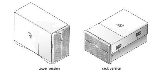
Figure 1-1 shows the rack and tower versions of your system. The illustrations in this document are based on the tower version with the system laying on its right side.
Figure 1-1. System Orientation
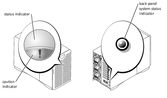
The system's front bezel has an indictor that shows the system status when the bezel is installed (see Figure 1-2). The status indicator signals that the system is operating normally or that it is being identified by the systems management software. The caution indicator signals problems with power supplies, system fans, power-supply fans, system temperature, hard drives, or expansion cards. The back-panel system status indicator functions the same way as the front-bezel indicator. Table 1-1 lists the system's status indicator codes and conditions.
Figure 1-2. System Status Indicators
|
Bezel Indicators |
Back-Panel Indicator |
Indicator Code | |
|---|---|---|---|
|
Status |
Caution | ||
Off | Off | Off | No power is available to the system, or the system is not powered on.1 |
On | Off | Blue | The system is operating normally. |
Off | Blinking | Amber blinking | The system has detected an error and requires attention.1 |
Blinking | Off | Blue blinking | The system is identifying itself. NOTE: Systems management software causes the status indicator to blink to identify a particular system. For more information, see your systems management software documentation. |
1 See your Installation and Troubleshooting Guide for more information. | |||
Additional indicators are located behind the front bezel for system power and hard drives. The CD and diskette drives have green activity indicators. The front-panel LCD provides status information using an alphanumeric character display (see "LCD Status Messages"). See Figure 1-3 for the front-panel indicators and features.
Figure 1-3. Front-Panel Indicators and Features
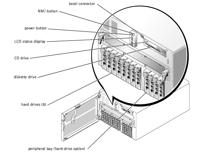
The power button is used to turn the power supplies on and off, while the NMI button is used for debugging (see your Installation and Troubleshooting Guide for more information).
 |
NOTE: If you turn off the system using the power button and the system is running an ACPI-compliant operating system (such as Microsoft® Windows® 2000), the system performs a graceful shutdown before the power is turned off. If the system is not running an ACPI-compliant operating system, the power is turned off immediately after the power button is pressed. |
The system's front-bezel indicator shows whether the system is operating correctly or whether it needs attention (see Figure 1-2). When the front-bezel indicator denotes an error condition, open the bezel for more information provided on the LCD.
The LCD displays two lines of five alphanumeric characters. The display codes are presented in two color combinations:
For more information about LCD codes, see your Installation and Troubleshooting Guide.
Each hard-drive carrier has two indicators that provide information on the status of the SCSI hard drive: a busy indicator and a status indicator (see Figure 1-4 and Table 1-2).
Figure 1-4. SCSI Hard-Drive Indicators
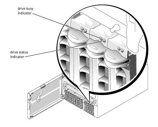
The drive busy indicator lights when data is transferred to or from the hard drive. The drive status indicator lights when the hard drive is active on the SCSI bus.
Table 1-2 lists the drive status indicator codes. Different codes are displayed as drive events occur in the system. For example, in the event of a hard-drive failure, the "drive failed" code appears. After the drive is selected for removal, the "drive being prepared for removal" code appears, followed by the "drive ready for insertion or removal" code. After the replacement drive is installed, the "drive being prepared for operation" code appears, followed by the "drive online" code.
|
Condition |
Indicator |
|---|---|
Drive bay empty, ready for insertion or removal | Off |
Drive being prepared for operation, drive online | Steady green |
Identify drive | Blinks green four times per second |
Drive being prepared for removal | Blinks green twice per second at equal intervals |
Drive rebuilding | Blinks green twice per second at unequal intervals |
Drive failed | Blinks amber four times per second |
Predicted failure for the drive | Blinks green, then amber, and then off, repeating this sequence every two seconds |
NOTE: The drive busy indicator signifies whether the hard drive is active on the SCSI bus. This indicator is controlled by the hard drive. | |
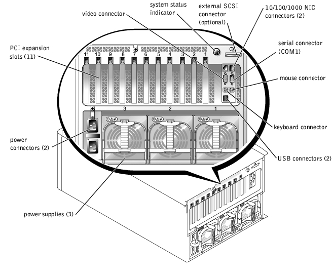
Figure 1-5 shows the back-panel indicators and features of the system.
|
NOTE: The back-panel system status indicator has the same functionality as the bezel indicator. When the system is operating normally, the back-panel indicator is blue. When the system needs attention, the amber indicator blinks. |
Figure 1-5. Back-Panel Indicators and Features
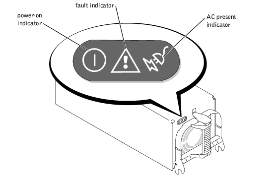
Each hot-pluggable power supply has three indicators that provide information on power status, faults, and the presence of power. Figure 1-6 shows the location of the indicators. Table 1-3 lists the conditions for each indicator.
Figure 1-6. Power-Supply Indicators
|
Indicator |
Condition |
|---|---|
Power-on | Green indicates that the power supply is operational. |
Fault | Red indicates a problem with the power supply (for example, a fan failure or voltage error). |
AC present | Green indicates that power is present at the power supply and that the system is connected to a power source. |
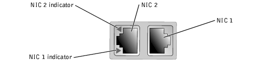
Each NIC has an indicator that provides information on network activity and link status. Figure 1-7 shows the location of the indicators. Table 1-4 lists the conditions for the indicators.
|
Indicator |
Condition |
|---|---|
Off | The NIC is not connected to the network. |
Green | The NIC is connected to a valid link partner. |
Amber blinking | Network data is being sent or received. |
Expansion slots 1 through 11 are hot-pluggable. Each expansion slot has a light pipe, visible through the back-panel vents, that indicates the status of the expansion card. Table 1-5 lists the conditions for the indicators.
|
Indicator |
Condition |
|---|---|
Off | Expansion-slot power is off. No action is required. |
Green | Expansion-slot power is on. No action is required. |
Green blinking fast | The expansion slot is being identified by an application program or driver. No action is required. |
Amber blinking slow | The expansion card is faulty or improperly installed, causing a problem with power supply to the card. |
Amber blinks twice, pauses, and then repeats the sequence | An expansion card with a slower operating speed was hot-plugged. If you are replacing an expansion card with a card that has a slower operating speed, you must power down the system before installing the replacement card. |
Your system offers the following features:
|
NOTE: If you decide to upgrade your system by installing an additional microprocessor, you must order the microprocessor upgrade kits from the company where you purchased your system. Not all versions of the Intel Xeon microprocessor will work properly as additional microprocessors. The upgrade kit contains the correct version of the microprocessor as well as the instructions for performing the upgrade. All microprocessors must have the same internal operating frequency and cache size. |
|
NOTE: All memory modules in a single memory bank must be the same size and type. |
The system also features redundant memory, which provides your system with a failover memory bank when a memory bank fails, and a memory mirror, which splits the four memory banks into a mirrored set.
|
NOTE: The failover memory bank is supported if three or four identical memory banks (12 or 16 memory modules) are installed on your system. Memory mirror is supported if four identical banks (16 memory modules) are installed on your system. Both features must be enabled or disabled in the BIOS setup and you cannot enable both features simultaneously. For more information, see "Using the System Setup Program." |
For more information about specific features, see "Technical Specifications."
The following software is included with your system:
Your system supports the following operating systems:
A number of devices are available to protect your system from the effects of power problems such as power surges, transients, and power failures. The following subsections describe some of these devices.
Surge protectors are available in a variety of types and usually provide a level of protection commensurate with the cost of the device. Surge protectors prevent overvoltage spikes, such as those that may occur during an electrical storm, from entering the system through the electrical outlet. Surge protectors do not offer protection against brownouts, which occur when the voltage drops more than 20 percent below the normal power line voltage level.
Line conditioners go beyond the overvoltage protection of surge protectors. Line conditioners keep a system's power source voltage at a fairly constant level and provide protection from brownouts of short duration. Because of this added protection, line conditioners cost more than surge protectors—up to several hundred dollars. However, these devices cannot protect against a complete loss of power.
UPS systems offer the most complete protection against variations in power because they use battery power to keep the system running when power is unavailable or unusable. The battery is charged by the AC power while it is available so that once power is lost, the battery can provide power to the system for a limited amount of time—from 15 minutes to an hour or so—depending on the UPS system.
UPS systems range in price from a few hundred dollars to several thousand dollars, with the more expensive units allowing you to run larger systems for a longer period of time when power is lost. UPS systems that provide only 5 minutes of battery power let you conduct an orderly shutdown of the system but are not intended to provide continued operation. Surge protectors should be used with all UPS systems, and the UPS system should be UL safety approved.
Besides this User's Guide, the following documentation is included with your system:
You may also have the following documents.
|
NOTE: Always read these updates before consulting any other documentation because the updates often contain information that supersedes information in the other documents. |
If at any time you do not understand a procedure described in this guide or if your system does not perform as expected, there are a number of tools are provided to assist you. For more information on these help tools, see "Getting Help" in your Installation and Troubleshooting Guide.