 Jumpers—A General Explanation
Dell™ PowerEdge™ 6600 Systems Installation and Troubleshooting Guide
I/O Riser Card Jumpers and Connectors
I/O Board Connectors and Buses
Microprocessor Board Connectors
SCSI Backplane Board Connectors
Peripheral Riser Card Connectors
Disabling a Forgotten Password
This section provides specific information about the jumpers on the system board. It also provides some basic information on jumpers and switches and describes the connectors and sockets on the various boards in the system.
Jumpers provide a convenient and reversible way of reconfiguring the circuitry on a printed circuit board. When reconfiguring the system, you may need to change jumper settings on the system board. You may also need to change jumper settings on expansion cards or drives.
Jumpers are small blocks on a circuit board with two or more pins emerging from them. Plastic plugs containing a wire fit down over the pins. The wire connects the pins and creates a circuit. To change a jumper setting, pull the plug off its pin(s) and carefully fit it down onto the pin(s) indicated. Figure A-1 shows an example of a jumper.


|
CAUTION: Make sure the system is turned off before you change a jumper setting. Otherwise, damage to the system or unpredictable results may occur. |
A jumper is referred to as open or unjumpered when the plug is pushed down over only one pin or if there is no plug at all. When the plug is pushed down over two pins, the jumper is referred to as jumpered. The jumper setting is often shown in text as two numbers, such as 1-2. The number 1 is printed on the circuit board so that you can identify each pin number based on the location of pin 1.
Figure A-2 shows the location and default settings of the jumper blocks on the system board. See Table A-1 for the designations, default settings, and functions of the system's jumpers.
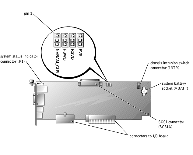
Figure A-2 shows the location of the configuration jumpers and connector on the I/O riser card. Table A-1 and Table A-2 list the jumpers and connectors.
Figure A-2. I/O Riser Card Components
|
Jumper |
Setting |
Description |
|---|---|---|
NVRAM_CLR |
| The configuration settings are retained at system boot. |
| The configuration settings are cleared at next system boot. (If the configuration settings become corrupted to the point where the system will not boot, change the jumper setting to 1–2 and boot the system. Change the jumper setting back to 2–3 before restoring the configuration information.) | |
PSWD |
| The password feature is enabled. |
| The password feature is disabled. | |
RSVD |
| Reserved (do not change). |
FVS |
| Reserved (do not change). |
NOTE: For the full name of an abbreviation or acronym used in this table, see "Abbreviations and Acronyms." | ||
|
Connector or Socket |
Description |
|---|---|
INTR | Chassis intrusion switch connector |
P1 | Back-panel system status indicator |
SCSIA | An external SCSI connector on the back panel or an internal tape drive |
VBATT | System battery socket |
NOTE: See Figure 2-3 for back-panel connectors provided by the I/O riser card. | |
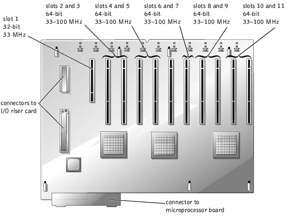
Figure A-3 shows the expansion slots, buses, and bus operating speeds.
Figure A-3. I/O Board Connectors and Buses
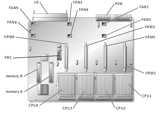
See Figure A-4 and Table A-3 for the location and description of the microprocessor board connectors.
Figure A-4. Microprocessor Board Connectors
|
Connector or Socket |
Description |
|---|---|
I/O | Interface connector for the microprocessor board and the I/O board |
FANn | Fan connectors 1 through 6 |
PDB | Interface connector for the microprocessor board and the power distribution board |
VRMn | VRM connectors 1 through 4 |
CPUn | Microprocessor sockets 1 through 4 |
MEMORYn | Memory riser card connectors A and B |
PRC | Peripheral riser card connector |
NOTE: For the full name of an abbreviation or acronym used in this table, see "Abbreviations and Acronyms." | |
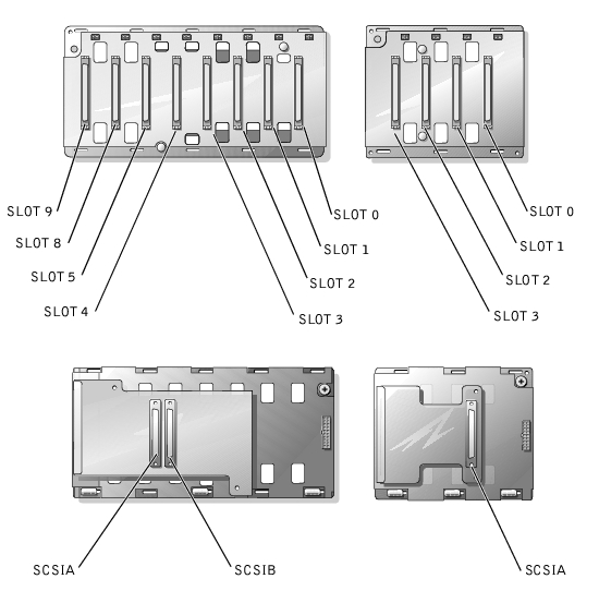
Figure A-5 shows the location of the connectors on each side of the SCSI backplane board.
Figure A-5. Connectors on the SCSI Backplane Board
See Figure A-6 and Table A-4 for the location and description of the peripheral riser card connectors.
Figure A-6. Peripheral Riser Card Connectors
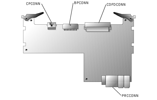
|
Connector or Socket |
Description |
|---|---|
CPCONN | Control panel cable connector |
BPCONN | Backplane power connector (not used) |
CDFDCONN | CD/diskette interface cable connector |
PRCCONN | Peripheral riser card connector |
NOTE: For the full name of an abbreviation or acronym used in this table, see "Abbreviations and Acronyms." | |
The system's software security features include a system password and a setup password, which are discussed in detail in "Using the System Setup Program" in the User's Guide. A password jumper on the I/O riser card enables these password features or disables them and clears any password(s) currently in use.
To disable a forgotten system password or setup password, perform the following steps.
|
|
CAUTION: See "Protecting Against Electrostatic Discharge" in the Safety Instructions in your System Information document. |
The existing passwords are not disabled (erased) until the system boots with the PSWD jumper plug removed. However, before you assign a new system and/or setup password, you must install the jumper plug.
 |
NOTE: If you assign a new system and/or setup password with the jumper plug still removed, the system disables the new password(s) the next time it boots. |
To assign a new passwords using the System Setup program, see "Assigning a System Password" in the User's Guide.