 System Orientation
Dell™ PowerEdge™ 2600 Systems User's Guide
Obtaining Technical Assistance
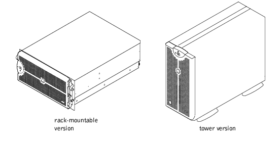
Your full-featured system may have one or two Intel® Xeon™ microprocessors. Your system comes in either a tower version, or rack-mountable version.
This section describes the major hardware and software features of your system and provides information about the system status indicators, and indicators on the system's front panel. It also provides information about other documents you may need when setting up your system and how to obtain technical assistance.
When following the procedures in this guide, assume that the locations or directions relative to the system are as shown in Figure 1-1. The illustrations in this document depict the tower version of the system lying on its side.
Figure 1-1. System Orientation
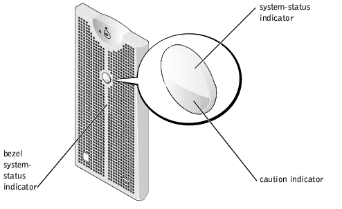
The system has indicators that can represent system status. When the bezel is installed, the bezel system-status indicator (see Figure 1-2) signifies when the system is operating properly, or when the system needs attention. A caution code signifies a problem with microprocessors, power supply, system or power-supply fans, system temperature, hard drives, system memory, expansion cards, or the integrated SCSI controller. When the bezel is off, the system-status indicators on the system (see Figure 1-3) assume the same functions as the bezel system-status indicator.
Table 1-1 lists the system's status indicator codes.
Figure 1-2. Bezel System-Status Indicator
|
System-Status Indicator |
Caution Indicator |
Indicator Code |
|---|---|---|
Off | Off | No power is available to the system, or the system is not powered on. |
On | Off | The system is operating normally. |
Off | Blinking | The system has detected an error and requires attention. |
Blinking | Off | The system is identifying itself. |
Blinking | Blinking or Off | Systems management software causes the status indicator to blink to identify a particular system. |
Additional indicators for system power and drives are located behind the bezel.
Figure 1-3 shows the front-panel features of the system. Table 1-2 describes the front-panel features.
Figure 1-3. Front-Panel Features

|
Component |
Description | ||
|---|---|---|---|
Power button | Turns system power off and on.
The button is enabled in the System Setup program. When disabled, the button can only turn system power on. | ||
Power indicators | Provides information about power status (see "Power Indicator"). | ||
Power-supply indicators | Provides information about power status (see Table 1-4). | ||
Status indicator | Provides information about when the system is operating properly, or when the system needs attention (see Table 1-1). | ||
Caution indicator | Provides information about when the system is operating properly, or when the system needs attention (see Table 1-1). | ||
CD and diskette drive indicators | Indicates read or write access to the respective drive. | ||
Hard-drive status indicators | Provides information about the status of the respective hard drive (see Table 1-5). | ||
NMI button | Troubleshoots software and device driver errors when using certain operating systems. You can press this button using the end of a paper clip. The NMI option is enabled in the System Setup program.
|
The system has indicators on the front panel and the power supplies that denote system power status (see Figure 1-3).
The power button controls the power input to the system's power supplies. The power-button indicator can provide information on power status.
Table 1-3 lists the power-button indicator codes.
|
Indicator |
Indicator Code |
|---|---|
On | Indicates that power is supplied to the system, and the system is operational. |
Off | Indicates that no power is supplied to the system. |
Blinking | Indicates that power is supplied to the system, but the system is in a standby state. For more information on standby states, see your operating system documentation. |
Each hot-pluggable power supply has indicators that provide information on power status, fault, and the presence of power (see Figure 1-4). Table 1-4 lists the power-supply indicator codes.
Figure 1-4. Power-Supply Indicators

|
Indicator |
Indicator Code |
|---|---|
Power-on | Green indicates that the power supply is operational. |
Fault | Red indicates a problem with the power supply (such as a fan failure or voltage error). |
Power present | Green indicates that power is present at the power supply and that the system is connected to a power source. |
Each hard-drive carrier has two indicators: a drive-busy indicator and a drive-status indicator (see Figure 1-5). The indicators provide information on the status of the respective hard drive. Table 1-5 lists the hard-drive status indicator codes.
Figure 1-5. Hard-Drive Status Indicators
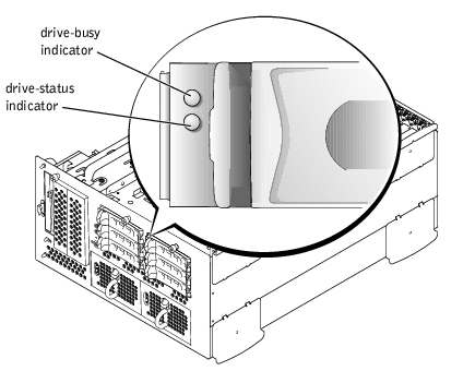
Different codes display as drive events occur in the system. For example, in the event of a hard-drive failure, the "drive fail" code appears. After the drive is selected for removal, the "prepared for removal" code appears. After the replacement drive is installed, the "prepared for operation, drive online" code appears.
|
Indicator |
Indicator Code |
|---|---|
Drive bay empty, ready for insertion or removal | Off |
Drive being prepared for operation, drive online | Steady green |
Identify drive | Blinks green four times per second |
Drive being prepared for removal | Blinks green twice per second at equal intervals |
Drive rebuilding | Blinks green twice per second at unequal intervals |
Drive failed | Blinks amber four times per second |
Predicted failure for the drive | Blinks green, then amber, and then off, repeating this sequence every two seconds |
Drive online | Steady green |
NOTE: The "drive busy" indicator signifies whether the hard drive is active on the SCSI bus. This indicator is controlled by the hard drive. | |
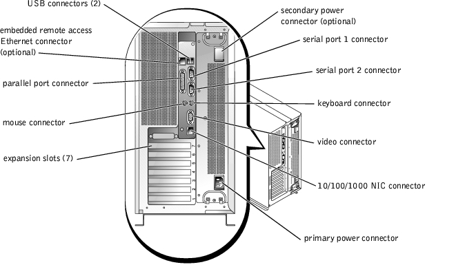
Figure 1-6 shows the back-panel features of the system. For specific information about the back-panel connectors, see "I/O Ports and Connectors."
Figure 1-6. Back-Panel Features
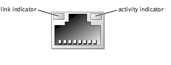
The NIC indicator on the back panel provides information on network activity and link status for the NIC (see Figure 1-7). Table 1-6 lists the NIC indicator codes.
|
Link Indicator |
Activity Indicator |
Indicator Code |
|---|---|---|
Off | Off | The NIC is not connected to the network. |
Green | Off | The NIC is connected to a valid link partner on the network. |
Green | Amber blinking | Network data is being sent or received. |
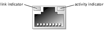
The embedded remote access Ethernet connector indicators on the back panel provide information on network activity and link status for the embedded remote access Ethernet connector (see Figure 1-8). Table 1-7 lists the embedded remote access Ethernet connector indicator codes.
Figure 1-8. Embedded Remote Access Ethernet Connector
|
Link Indicator |
Activity Indicator |
Indicator Code |
|---|---|---|
Off | Off | The NIC is not connected to the network. |
Green | Amber | The NIC is connected to a valid link partner on the network. |
Green | Amber blinking | Network data is being sent or received. |
For more information about specific features, see "Technical Specifications."
The following software is included with your system:
Your system may also support other operating systems such as Novell® NetWare®.
A number of optional devices are available to protect your system from the effects of power problems such as power surges, transients, and power failures. The following subsections describe some of these devices.
Surge protectors are available in a variety of types and usually provide a level of protection commensurate with the cost of the device. Surge protectors prevent overvoltage spikes, such as those that may occur during an electrical storm, from entering the system through the electrical outlet. Surge protectors do not offer protection against brownouts, which occur when the voltage drops more than 20 percent below the normal AC line voltage level.
Line conditioners go beyond the overvoltage protection of surge protectors. Line conditioners keep a system's AC power source voltage at a fairly constant level and provide protection from brownouts of short duration. Because of this added protection, line conditioners cost more than surge protectors—up to several hundred dollars. However, these devices cannot protect against a complete loss of power.
UPS systems offer the most complete protection against variations in power because they use battery power to keep the system running when AC power is unavailable or unusable. The battery is charged by the AC power while it is available so that once AC power is lost, the battery can provide power to the system for a limited amount of time—from 15 minutes to an hour or so—depending on the UPS system.
UPS systems that provide only 5 minutes of battery power allow you to conduct shutdown of the system but are not intended to provide continued operation. Use surge protectors with all UPS systems, and ensure that the UPS systems are UL safety approved.
The following documentation is included with your system:

|
CAUTION: The System Information document provides important safety and regulatory information. Warranty information may or may not be included within this document. |
You may also have the following documents:
 |
NOTE: Always read these updates before consulting any other documentation because the updates often contain information that supersedes the information in the other documents. |
If at any time you do not understand a procedure described in this guide or if your system does not perform as expected, a number of tools are provided to assist you. For more information on these help tools, see "Getting Help" in your Installation and Troubleshooting Guide.
