 I/O Connectors
Dell™ PowerEdge™ 1750 Systems Installation and Troubleshooting Guide
PS/2-Compatible Keyboard and Mouse Connectors
I/O connectors are the gateways that the system uses to communicate with external devices, such as a keyboard, mouse, printer, or monitor. This section describes the various connectors on your system. If you reconfigure the hardware connected to the system, you may also need the pin number and signal information for these connectors. Figure B-1illustrates the I/O connectors on the system back panel; Figure B-2 identifies the I/O connectors on the front panel.
Figure B-1. I/O Connectors on Back Panel
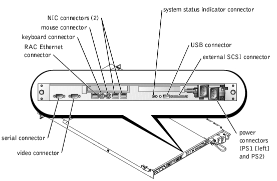
Figure B-2. I/O Connectors on Front Panel
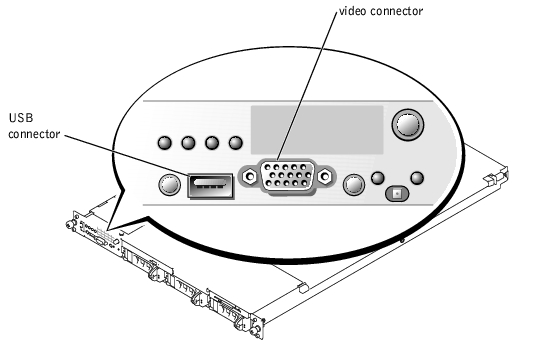
Table B-1 shows the icons used to label the connectors on the system.
|
Icon |
Connector |
|---|---|
| |
| |
| |
| |
| |
| |
|
Serial connectors support devices such as external modems, printers, and mice that require serial data transmission. The serial connector uses a 9-pin D-subminiature connector.
The default designation of the integrated serial connector is COM1. When you add an expansion card containing a serial connector that has the same designation as the integrated connector, the system's autoconfiguration feature remaps (reassigns) the integrated serial connector to the next available designation. Both the new and the remapped COM connectors share the same IRQ setting. COM1 and COM3 share IRQ4, while COM2 and COM4 share IRQ3.
 |
NOTE: If two COM connectors share an IRQ setting, you may not be able to use them both at the same time. In addition, if you install one or more expansion cards with serial connectors designated as COM1 and COM3, the integrated serial connector is disabled. |
Before adding a card that remaps the COM connectors, check the documentation that came with the software to make sure that the software can accommodate the new COM connector designation.
Figure B-3 illustrates the pin numbers for the serial connector and Table B-2 defines the pin assignments for the connector.
Figure B-3. Serial Connector Pin Numbers
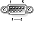
Table B-2. Serial Connector Pin Assignments
|
Pin |
Signal |
I/O |
Definition |
|---|---|---|---|
The PS/2-compatible keyboard and mouse cables attach to 6-pin, miniature DIN connectors. Figure B-4 illustrates the pin numbers for these connectors and Table B-3 defines the pin assignments for these connectors.
Figure B-4. PS/2-Compatible Keyboard and Mouse Connector Pin Numbers

Table B-3. Keyboard and Mouse Connector
Pin Assignments
|
Pin |
Signal |
I/O |
Definition |
|---|---|---|---|
You can attach a VGA-compatible monitor to the system's integrated video controller using a 15-pin high-density D-subminiature connector. Figure B-5 illustrates the pin numbers for the video connector and Table B-4 defines the pin assignments for the connector.
|
NOTE: Installing a video card automatically disables the system's integrated video controller. |
Figure B-5. Video Connector Pin Numbers
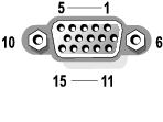
Table B-4. Video Connector Pin Assignments
|
Pin |
Signal |
I/O |
Definition |
|---|---|---|---|
The system's USB connector supports USB-compliant peripherals such as keyboards, mice, and printers and may also support USB-compliant devices such as diskette drives and CD drives. Figure B-6 illustrates the pin numbers for the USB connector and Table B-5 defines the pin assignments for the connector.
 |
NOTICE: Do not attach a USB device or a combination of USB devices that draw a maximum current of more than 500 mA per channel or +5 V. Attaching devices that exceed this threshold may cause the USB connectors to shut down. See the documentation that accompanied the USB devices for their maximum current ratings. |
Figure B-6. USB Connector Pin Numbers

Table B-5. USB Connector Pin Assignments
|
Pin |
Signal |
I/O |
Definition |
|---|---|---|---|
The system's optional RAC circuitry is designed to provide remote access capabilities for the system. It is designed specifically to work with systems management software. Figure B-7 illustrates the pin numbers for the RAC Ethernet connector and Table B-6 defines the pin assignments for the connector.
Figure B-7. RAC Ethernet Connector
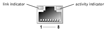
Table B-6. RAC Ethernet Connector Pin Assignments
|
Pin |
Signal |
I/O |
Definition |
|---|---|---|---|
The system's integrated NIC functions as a separate network expansion card while providing fast communication between servers and workstations. Figure B-8 illustrates the pin numbers for the NIC connector and Table B-7 defines the pin assignments for the connector.
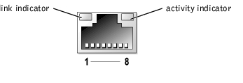
Table B-7. NIC Connector Pin Assignments
|
Pin |
Signal |
I/O |
Definition |
|---|---|---|---|
The NIC supports a UTP Ethernet cable equipped with a standard RJ45-compatible plug. Observe the following cabling restrictions.
|
NOTICE: To avoid line interference, voice and data lines must be in separate sheaths. |
For detailed guidelines on operation of a network, see "Systems Considerations of Multi-Segment Networks" in the IEEE 802.3 standard.