 Indicators on the Optional Bezel
Dell™ PowerEdge™ 1650 Systems User's Guide
Indicators on the Optional Bezel
Front-Panel Features and Indicators
Back-Panel Features and Indicators
Obtaining Technical Assistance
Your system is an ultra-slim, full-featured, highly available, rack-mount system equipped with one or two Intel® Pentium® III microprocessors.
This section describes the major hardware and software features of your system and provides information about the indicators on the system's front and back panels. It also provides information about other documents you may need when setting up your system and how to obtain technical assistance.
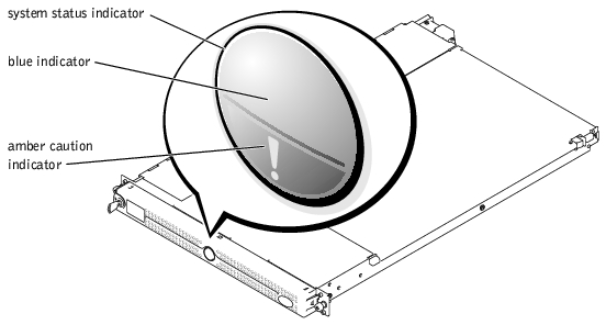
The optional system bezel incorporates a system status indicator divided into blue and amber system status indicators (see Figure 1-1). The blue indicator lights up when the system is operating correctly. The amber indicator lights up when the system needs attention due to a problem with power supplies, fans, system temperature, or hard drives.
Table 1-1 lists the system's indicator patterns. Different patterns are displayed as events occur in the system.
Figure 1-1. System Status Indicators
|
Blue indicator |
Amber indicator |
Description |
|---|---|---|
Off | Off | There is no power available to the system, or power is available to the system, but the system is not powered on.1 |
Off | Blinking | The system has detected an error.1 |
On | Off | Power is on, and the system is operational. |
Blinking | Off | The indicator has been activated to identify the system in a rack. |
1 See your Installation and Troubleshooting Guide for more information. NOTE: While the system is being identified, the blue indicator will blink even though an error has been detected. Once the system is identified, the blue indicator ceases blinking and the amber indicator resumes blinking. | ||
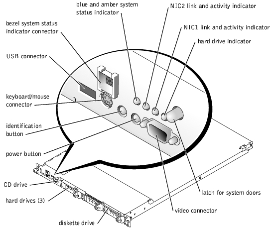
Figure 1-2 shows the controls, indicators, and connectors located behind the optional bezel on the system's front panel.
Figure 1-2. Front-Panel Features and Indicators
 |
NOTE: If you turn off the system using the power button and the system is running an ACPI-compliant operating system (such as Microsoft® Windows® 2000), the system performs a graceful shutdown before the power is turned off. If the system is not running an ACPI-compliant operating system, the power is turned off immediately after the power button is pressed. |
The front panel also incorporates a USB connector, a video connector, and a PS/2 connector to connect a mouse and keyboard using a Y-cable (see Figure 1-2).
|
LED Indicator |
Icon |
Description |
|---|---|---|
blue and amber system status indicator |
| The blue system status indicator lights up during normal system operation. The server management software can also cause the blue system status indicator to flash to identify a particular system. The amber system status indicator flashes when the system needs attention due to a problem with power supplies, fans, system temperature, or hard drives. NOTE: If the system is connected to AC power and an error has been detected, the amber system status indicator will flash regardless of whether the system has been powered on. |
NIC1 and NIC2 link and activity indicators |
| The link and activity indicators for the two integrated NICs light when the NICs are in use. |
hard-drive indicator |
| The green hard-drive activity indicator flashes when the hard drives are in use (see Figure 1-3 for more information on hard-drive indicators). |
power button |
| The power button lights when the system power is on. |
If the optional RAID on motherboard (ROMB) card is activated, two indicators on each of the hard-drive carriers provide information on the status of the SCSI hard drives (see Figure 1-3 and Table 1-3). The SCSI backplane firmware controls the drive power-on/fault indicator.
|
NOTE: The following indicators are for SCSI hard drives only. The indicator for the optional IDE hard drives is located on the control panel on the front of the system. See Figure 1-2 for location of hard-drive indicator on the front panel. |
Figure 1-3. SCSI Hard-Drive Indicators
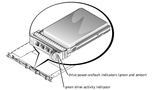
Table 1-3 lists the drive indicator patterns. Different patterns are displayed as drive events occur in the system. For example, in the event of a hard-drive failure, the "drive failed" pattern appears. After the drive is selected for removal, the "drive being prepared for removal" pattern appears, followed by the "drive ready for insertion or removal" pattern. After the replacement drive is installed, the "drive being prepared for operation" pattern appears, followed by the "drive online" pattern.
|
NOTE: If the optional ROMB card is not installed, you will see only the "drive online" indicator pattern. You will also see the drive-activity indicator blink when the drive is being accessed. |
|
Condition |
Indicator Pattern |
|---|---|
Identify drive | The green power-on/fault indicator blinks 4 times per second. |
Drive being prepared for removal | The green power-on/fault indicator blinks 2 times per second. |
Drive ready for insertion or removal | Both drive indicators are off. |
Drive being prepared for operation | The green power-on/fault indicator is on. |
Drive predicted failure | The power-on/fault indicator slowly blinks green, amber, and off. |
Drive failed | The amber power-on/fault indicator blinks 4 times per second. |
Drive rebuilding | The green power-on/fault indicator blinks slowly. |
Drive online | The green power-on/fault indicator is on. |
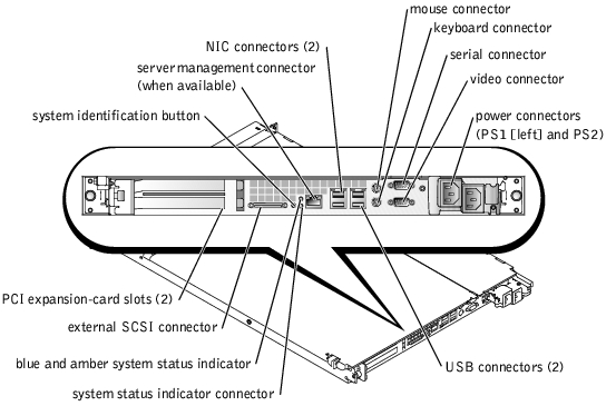
Figure 1-4 shows the controls, indicators, and connectors located on the system's back panel.
|
NOTE: Systems with only one power supply should connect the power cable to connector PS1 (see Figure 1-4). |
Figure 1-4. Back-Panel Features and Indicators
Your system offers the following features:
|
NOTE: If you decide to upgrade your system by installing a second microprocessor, you must order the microprocessor upgrade kits from Dell. Not all versions of the Pentium III microprocessor will work properly as additional microprocessors. The upgrade kit from Dell contains the correct version of the microprocessor as well as the instructions for performing the upgrade. Both microprocessors must have the same internal operating frequency and cache size. |
The system board includes the following features:
For more information about specific features, see "Technical Specifications."
The following software is included with your system:
Your system supports the following operating systems:
A number of devices are available to protect your system from the effects of power problems such as power surges, transients, and power failures. The following subsections describe some of these devices.
Surge protectors are available in a variety of types and usually provide a level of protection commensurate with the cost of the device. Surge protectors prevent overvoltage spikes, such as those that may occur during an electrical storm, from entering the system through the electrical outlet. Surge protectors do not offer protection against brownouts, which occur when the voltage drops more than 20 percent below the normal AC line voltage level.
Line conditioners go beyond the overvoltage protection of surge protectors. Line conditioners keep a system's AC power source voltage at a fairly constant level and provide protection from brownouts of short duration. Because of this added protection, line conditioners cost more than surge protectors—up to several hundred dollars. However, these devices cannot protect against a complete loss of power.
UPS systems offer the most complete protection against variations in power because they use battery power to keep the system running when AC power is unavailable or unusable. The battery is charged by the AC power while it is available so that once AC power is lost, the battery can provide power to the system for a limited amount of time—from 15 minutes to an hour or so—depending on the UPS system.
UPS systems range in price from a few hundred dollars to several thousand dollars, with the more expensive units allowing you to run larger systems for a longer period of time when AC power is lost. UPS systems that provide only 5 minutes of battery power let you conduct an orderly shutdown of the system but are not intended to provide continued operation. Surge protectors should be used with all UPS systems, and the UPS system should be UL safety approved.
Besides this User's Guide, the following documentation is included with your system:
You may also have the following documents.
|
NOTE: Documentation updates are sometimes included with the system to describe changes to the system or software. Always read these updates before consulting any other documentation because the updates often contain information that supersedes the information in the other documents. |
If at any time you do not understand a procedure described in this guide or if your system does not perform as expected, a number of tools are provided to assist you. For more information on these help tools, see "Getting Help" in your Installation and Troubleshooting Guide.