Serial Port
Dell™ PowerEdge™ 1650 Systems User's Guide
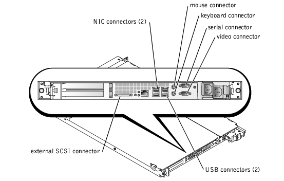
The I/O ports and connectors on your system are the gateways through which the system communicates with external devices such as a keyboard, mouse, and monitor. Figure B-1 identifies front-panel I/O ports and connectors. Figure B-2 identifies back-panel I/O ports and connectors.
Figure B-1. Front-Panel I/O Ports and Connectors
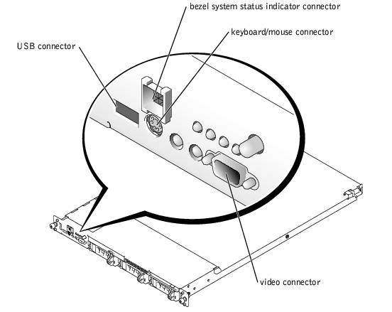
Figure B-2. Back-Panel I/O Ports and Connectors
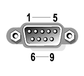
The integrated serial port uses 9-pin D-subminiature connectors on the back panel. This ports supports devices such as external modems, printers, plotters, and mice that require serial data transmission (the transmission of data one bit at a time over one line).
Most software uses the term COM (for communications) plus a number to designate a serial port. The default designation for your system's integrated serial port is COM1.
If you reconfigure your hardware, you may need pin number and signal information for the serial port connector. Figure B-3 illustrates the pin numbers for the serial port connector and Table B-1 defines the pin assignments and interface signals for the serial port connector.
Figure B-3. Pin Numbers for the Serial Port Connector
|
Pin |
Signal |
I/O |
Definition |
|---|---|---|---|
1 | DCD | I | Data carrier detect |
2 | SIN | I | Serial input |
3 | SOUT | O | Serial output |
4 | DTR | O | Data terminal ready |
5 | GND | N/A | Signal ground |
6 | DSR | I | Data set ready |
7 | RTS | O | Request to send |
8 | CTS | I | Clear to send |
9 | RI | I | Ring indicator |
Shell | N/A | N/A | Chassis ground |
The system has an autoconfiguration capability for the serial ports. This feature lets you add an expansion card containing a serial port that has the same designation as one of the integrated ports, without having to reconfigure the card. When the system detects the duplicate serial port on the expansion card, it remaps (reassigns) the integrated port to the next available port designation.
Both the new and the remapped COM ports share the same IRQ setting, as follows:
COM1, COM3: IRQ4 (shared setting)
COM2, COM4: IRQ3 (shared setting)
These COM ports have the following I/O address settings:
COM1: 3F8h
COM2: 2F8h
COM3: 3E8h
COM4: 2E8h
For example, if you add an internal modem card with a port configured as COM1, the system then sees logical COM1 as the address on the modem card. It automatically remaps the integrated serial port that was designated as COM1 to COM3, which shares the COM1 IRQ setting. (Note that when you have two COM ports sharing an IRQ setting, you can use either port as necessary but you may not be able to use them both at the same time.) If you install one or more expansion cards with serial ports designated as COM1 and COM3, the corresponding integrated serial port is disabled.
Before adding a card that remaps the COM ports, check the documentation that accompanied your software to make sure that the software can be mapped to the new COM port designation.
To avoid autoconfiguration, you may be able to reset jumpers on the expansion card so that the card's port designation changes to the next available COM number, leaving the designation for the integrated port as is. Alternatively, you can disable the integrated ports through the System Setup program. The documentation for your expansion card should provide the card's default I/O address and allowable IRQ settings. It should also provide instructions for readdressing the port and changing the IRQ setting, if necessary.
For general information on how your operating system handles serial and parallel ports, and for more detailed command procedures, see your operating system documentation.
The system uses a PS/2-style keyboard and supports a PS/2-compatible mouse. Cables from both devices attach to 6-pin, miniature DIN connectors on the front and back panels of your system.
Mouse driver software can give the mouse priority with the microprocessor by issuing IRQ12 whenever a new mouse movement is detected. The driver software also passes along the mouse data to the application program that is in control.
If you reconfigure your hardware, you may need pin number and signal information for the keyboard connector. Figure B-4 illustrates the pin numbers for the keyboard connector. Table B-2 and Table B-3 defines the pin assignments and interface signals for the keyboard connector.
Figure B-4. Pin Numbers for the Keyboard Connector

Table B-2. Keyboard Connector Pin Assignments Pin Signal I/O Definition 1 KBDATA I/O Keyboard data 2 NC N/A No connection 3 GND N/A Signal ground 4 FVcc N/A Fused supply voltage 5 KBCLK I/O Keyboard clock 6 NC N/A No connection Shell N/A N/A Chassis ground Table B-3. Keyboard/Mouse Combination Connector Pin Signal I/O Definition 1 KBDATA I/O Keyboard data 2 MSDATA I/O Mouse data 3 GND N/A Signal ground 4 FVcc N/A Fused supply voltage 5 KBCLK I/O Keyboard clock 6 MSCLK I/O Mouse clock Shell N/A N/A Chassis ground
(Back Panel)
Pin Assignments (Front Panel)
If you reconfigure your hardware, you may need pin number and signal information for the mouse connector. Figure B-5 and illustrates the pin numbers for the mouse connector. Table B-4 defines the pin assignments and interface signals for the mouse connector.
Figure B-5. Pin Numbers for the Mouse Connector

|
Pin |
Signal |
I/O |
Definition |
1 | MSDATA | I/O | Mouse data |
2 | NC | N/A | No connection |
3 | GND | N/A | Signal ground |
4 | FVcc | N/A | Fused supply voltage |
5 | MSCLK | I/O | Mouse clock |
6 | NC | N/A | No connection |
Shell | N/A | N/A | Chassis ground |
 |
NOTE: This system provides two video connectors, one on the back panel and one on the front panel. If the monitor is connected to the front panel video connector, the back-panel video connector is disabled. The keyboard and mouse must be connected to the same panel as the monitor. For example, if the monitor is connected to the front-panel video connector, the keyboard and mouse must also be connected to the front-panel keyboard/mouse connector. This connector is a PS/2 connector and the keyboard connection is the default. To use both a keyboard and mouse from the front-panel connector, you must use a splitter cable (Y-cable). |
The system uses a 15-pin high-density D-subminiature connector on the front and back panels for attaching a VGA-compatible monitor to your system. The video circuitry on the system board synchronizes the signals that drive the red, green, and blue electron guns in the monitor.
If you reconfigure your hardware, you may need pin number and signal information for the video connector. Figure B-6 illustrates the pin numbers for the video connector, and Table B-5 defines the pin assignments and interface signals for the video connector.
Figure B-6. Pin Numbers for the Video Connector

Table B-5. Video Connector Pin Assignments Pin Signal I/O Definition 1 RED O Red video 2 GREEN O Green video 3 BLUE O Blue video 4 NC N/A No connection 5–8, 10 GND N/A Signal ground 9 VCC N/A Vcc 11 NC N/A No connection 12 DDC data out O Monitor detect data 13 HSYNC O Horizontal synchronization 14 VSYNC O Vertical synchronization 15 DDC clock out O Monitor detect clock Shell N/A N/A Chassis ground
Your system contains a single USB connector on the front control panel and two USB connectors on the back panel for attaching USB-compliant devices. USB devices are typically peripherals such as mice, keyboards, and system speakers.
 |
NOTICE: Do not attach a USB device or a combination of USB devices that draw a maximum current over 500 mA per channel or +5 V. Attaching devices that exceed this threshold may cause the USB ports to shut down. See the documentation that accompanied the USB devices for their maximum current ratings. |
If you reconfigure your hardware, you may need pin number and signal information for the USB connectors. Figure B-7 illustrates the USB connector and Table B-6 defines the pin assignments and interface signals for the USB connector.
Figure B-7. Pin Numbers for the USB Connector

Table B-6. USB Connector Pin Assignments Pin Signal I/O Definition 1 Vcc N/A Supply voltage 2 DATA- I/O Data 3 DATA+ I/O Data 4 GND N/A Signal ground
Your system has two integrated 10/100/1000-Mbps NICs. The 10/100/1000-Mbps NICs provide faster communication between servers and workstations and efficient utilization of host resources, freeing more of the system resources for other applications. The NICs support 10 Base-T, 100 Base-TX, and 1000 Base-T Ethernet standards.
Both NICs include a Wakeup On LAN feature that enables the system to be started by a special LAN signal from a server management console. Wakeup On LAN provides remote system setup, software downloading and installation, file updates, and asset tracking after hours and on weekends when LAN traffic is typically at a minimum.
|
NOTE: If Dell OpenManage™ IT Assistant is installed, the Wakeup On LAN feature may not function properly. See the Dell | Support website at support.dell.com for information about configuring Wakeup On LAN. |
Your system's RJ45 NIC connectors are designed for attaching a UTP Ethernet cable equipped with standard RJ45-compatible plugs. Press one end of the UTP cable into the NIC connector until the plug snaps securely into place. Connect the other end of the cable to an RJ45 jack wall plate or to an RJ45 port on a UTP concentrator or hub, depending on your network configuration. Observe the following cabling restrictions for 10 Base-T, 100 Base-TX, and 1000 Base-T networks.
|
NOTICE: To avoid line interference, voice and data lines must be in separate sheaths. |