 Installing Devices in the External Drive Bay
Dell™ PowerEdge™ 1500SC Systems Installation and Troubleshooting Guide
Installing Devices in the External Drive Bay
Removing and Replacing Front-Panel Inserts
SCSI Configuration Information
Installing a Tape Drive That Uses a Controller Card
Installing a Host-Adapter Expansion Card
The external drive bays of your system hold up to three user-accessible, half-height 5.25-inch devices (typically CD or tape drives). A CD drive is standard in the first external drive bay, while two additional devices of your choice can be installed in the next two external drive bays. A fourth drive bay accommodates a standard 3.5-inch diskette drive, which is controlled by the diskette drive controller on the system board.
The hard drive bays provide space for up to six 1-inch hard drives. These hard drives are hot-pluggable.
A CD drive is standard in the first external drive bay, while two additional devices of your choice can be installed in the next two external drive bays.
This section describes how to install the following options:
To remove or install drives in the external bays, you must remove the system covers. See "Removing and Replacing the System Covers" in "Troubleshooting Your System."
To protect the inside of the computer from foreign particles, a plastic insert covers each empty external drive bay. Additionally, each empty external drive bay is covered by a metal insert to maintain the necessary electromagnetic interference (EMI) shielding for the chassis. Before you install a drive in an empty bay, you must first remove the plastic and metal inserts. Whenever you remove a drive, be sure to replace the metal insert on the chassis and then replace the plastic insert in the front bezel to cover the empty bay.
This section describes the interface cables and power cables used with the drives in your system.
Most interface connectors are keyed for correct insertion; that is, a notch or a raised tab on one connector matches a tab or a notch on the other connector. Keying ensures that the pin-1 wire in the cable goes to the pin-1 ends of the connectors on both ends.
When you disconnect an interface cable, take care to grasp the cable connector, rather than the cable itself, to avoid stress on the cable.
Each drive in the external drive bays must connect to a 4-wire DC power cable from the system power supply. The connectors on these cables are labeled "P3," "P4," "P5," and "P6." Connectors P3, P4, and P5 are used for 5.25-inch devices; connector P6 is used for the 3.5-inch diskette drive.
Although SCSI devices are installed essentially the same way as other devices, their configuration requirements are different. To configure SCSI devices installed in the external bays, follow the guidelines in the following subsections.
Each device attached to the SCSI host adapter must have a unique SCSI ID number from 0 to 7.
When SCSI devices are shipped, the default SCSI ID numbers are assigned as follows:
 |
NOTE: There is no requirement that SCSI ID numbers be assigned sequentially or that devices be attached to the cable in order by ID number. |
SCSI logic requires that the two devices at opposite ends of the SCSI chain be terminated and that all devices in between be unterminated. The SCSI cable included in your system has an active terminator installed at the end of the cable. Disable the termination on all SCSI devices you attach to this cable.
This subsection describes how to install and configure SCSI hard drives in the system's internal hard drive bays, and how to upgrade the system by installing a host adapter expansion card.
The internal hard drive bays provide space for up to six 1-inch hard drives. These drives connect to a SCSI backplane board. A SCSI cable connects the SCSI backplane board to the SCSI host adapter connector on the system board or to an optional SCSI host adapter card.
Before attempting to remove or install a drive while the system is running, see the documentation for the host adapter card to ensure that the card is configured correctly to support hot-pluggable drive removal and insertion.
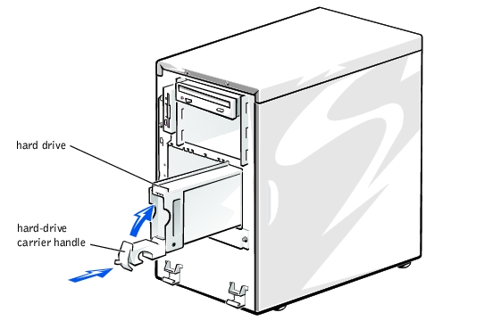
SCSI hard drives are supplied in special drive carriers that fit in the hard drive bays.
|
NOTE: We recommend that you use only drives that has been tested and approved for use with the SCSI backplane board. |
See the following guidelines when you configure the SCSI drive:
 |
NOTICE: Do not turn off or reboot your system while the drive is being formatted. Doing so can cause a drive failure. |
When you format a high-capacity SCSI hard drive, allow enough time for the formatting to be completed. Long format times for these drives are normal. A 9 GB hard drive, for example, can take up to 2.5 hours to format.
|
NOTICE: Hot-plug drive installation is not supported for systems without a host adapter expansion card. |
Figure 7-1. Installing a SCSI Hard Drive
|
NOTICE: Hot-plug drive installation is not supported for systems without a host adapter expansion card. |
If the drive has been online, the drive status indicators will flash sequentially as the drive is powered down. When all indicators are turned off, the drive is ready for removal.

|
CAUTION: See "Protecting Against Electrostatic Discharge" in the safety instructions in your System Information document. |
Ground yourself by touching an unpainted metal surface on the back of the computer, unpack the drive, and compare the jumper and switch settings with those in the drive documentation. (See "SCSI Configuration Information," for information on setting the drive's SCSI ID number and enabling termination [if required].) Change any settings necessary for this system's configuration.
If the drive does not already have drive rails attached, attach a drive rail to each side of the drive and secure each drive rail to the drive with a screw in each of the lower slotted screw holes on the drive rail.
Figure 7-2. Installing and Removing a 5.25-Inch Device
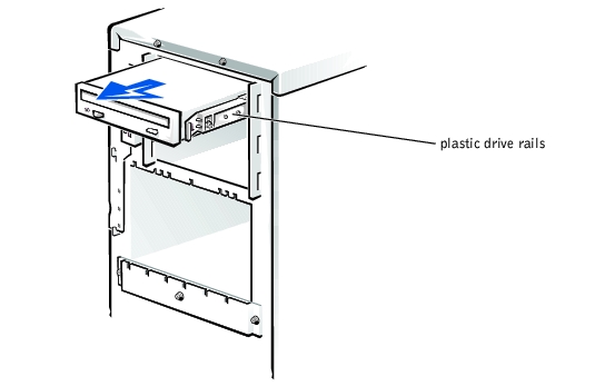
If necessary, you can adjust drive alignment by repositioning one or both rails.
Tape drives that require their own separate controller cards are shipped with the controller card and an interface cable.
 |
WARNING: Before you perform this procedure, you must turn off the system and disconnect it from its power source. For more information, see "Safety First— For You and Your System" in "Troubleshooting Your System." |
|
|
CAUTION: See "Protecting Against Electrostatic Discharge" in the safety instructions in your System Information document. |
If necessary, you can adjust drive alignment by repositioning one or both rails.
See the controller card's documentation to identify the controller connector on the card.
Arrange the cables so that they will not catch on the system covers or block the airflow of the fans or cooling vents.
|
WARNING: Before you perform this procedure, you must turn off the system and disconnect it from its power source. For more information, see "Safety First— For You and Your System" in "Troubleshooting Your System." |
|
|
CAUTION: See "Protecting Against Electrostatic Discharge" in the safety instructions in your System Information document. |
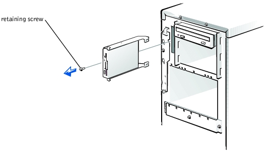
Figure 7-3. Removing and Installing a Diskette Drive
|
WARNING: Before you perform this procedure, you must turn off the system and disconnect it from its power source. For more information, see "Safety First— For You and Your System" in "Troubleshooting Your System." |
|
|
CAUTION: See "Protecting Against Electrostatic Discharge" in the safety instructions in your System Information document. |
Follow these general guidelines when installing a host-adapter expansion card. For specific instructions, see the documentation supplied with the host-adapter expansion card.
|
WARNING: Before you perform this procedure, you must turn off the system and disconnect it from its power source. For more information, see "Safety First— For You and Your System" in "Troubleshooting Your System." |
|
|
CAUTION: See "Protecting Against Electrostatic Discharge" in the safety instructions in your System Information document. |
See the documentation accompanying the expansion card.
To identify the correct connector, see documentation for the host-adapter expansion card. Route the SCSI cable under the front fan assembly.
If you are attaching multiple external SCSI devices, daisy-chain the devices to each other by using the cables shipped with each device.
Test a SCSI hard drive by running the SCSI Controllers test in system diagnostics. To test a SCSI tape drive, also see the documentation for the tape drive software to perform a tape drive backup and verification test.
If you plan to boot the system from a hard drive, the drive must be attached to the primary (or boot) controller or SCSI host adapter card. The device that the system boots from is determined by the boot order specified in the System Setup program.
The system setup program provides options that the system uses to scan for installed boot devices. See your system's User's Guide for information about the System Setup program.