Back to Contents Page
Dell™ PowerEdge™ 1655MC Systems
User's Guide
 Server Module Status Features
 Back-Panel Features
 System Features
 Supported Operating Systems
 Power Protection Devices
 Other Documents You May Need
 Obtaining Technical Assistance
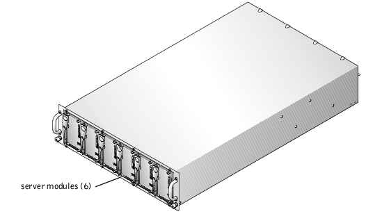
Your system can include up to six server modules (or blades). Each server module functions as an individual system encompassing up to two microprocessors, up to two hard drives, and up to two memory modules (see Figure 1-1). To function as a system, a server module is inserted into a chassis which includes power supplies, fans, a system management module, and at least one network switch module. The power supplies, fans, system management module, and network switch module are shared resources of the server modules in the chassis. In addition, your system may also ship with a USB diskette drive and a USB CD drive, which you can use for system setup and configuration.
Figure 1-1. System Overview
This section describes the major hardware and software features of your system and provides information about the indicators on the system's front and back panels. It also provides information about other documents you may need when setting up your system and how to obtain technical assistance.
Each server module has five indicators and one power button on the front of the server module (see Figure 1-2). The indicators include a status indicator, two network link indicators, a hard-drive activity indicator, and a power indicator. The server module has a USB port on the front of the module. The USB port is used to connect either the USB diskette drive or USB CD drive.
 |
NOTE: The USB port can only be used with the USB diskette drive or USB CD drive
supplied by Dell. The USB port will not operate properly with any other USB device.
|
Figure 1-2. Server Module Indicators
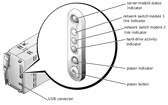
Table 1-1 provides information about the status indicators.
Table 1-1. Server Module Status Features
|
Indicator Type
|
Indicator
|
Indicator Code
|
|---|
Status indicator | Off | Power is not available to the server module, the server module is not powered on, or the server module is initializing. |
| Blue | The module is operating normally. |
| Blue blinking | The module is identifying itself. NOTE: Systems management software causes the indicator
to blink to identify a particular module.
|
| Amber | The system management module is not installed. |
| Amber blinking | Indicates a fault with the system or server module. |
Network switch module link indicators (2) | Off | Indicates that the server module does not have a link to the network switch module. |
| Green on | Indicates that the server module has a valid link to the network switch module. NOTE: If only one network switch module is installed, only
one link indicator will operate.
|
| Green blinking | Indicates network activity between the external network and the network switch module. |
Hard-drive activity indicator | Green blinking | Indicates hard drive activity. |
Power indicator | Green blinking | Indicates that the module is installed correctly and can be powered on by pressing the power button. |
| Green (steady) | Indicates that power is supplied to the server module, and the module is operational. |
| Amber blinking | Indicates a power fault or other condition that causes the server module to shut down. |
Power button | None | Turns server module power off and on. - If you turn off the module using the power button, and the module is running an ACPI-compliant operating system, the module can perform an orderly shutdown before the power is turned off.
- If the module is not running an ACPI-compliant operating system, power is turned off immediately after the power button is pressed.
The button is enabled in the System Setup program. When disabled, you can only use the button to turn on the server module. |
 |
NOTE: If the hard-drive activity indicator and the link indicators blink one after
another, the server module is initializing. The initialization time varies based on the
number of server modules installed and network activity.
|
Each server module has a USB port on the front of the server module, which allows you to connect a USB diskette drive or USB CD drive. The drives are used to configure the server module.
 |
NOTE: The USB port can only be used with the USB diskette drive or USB CD drive
supplied by Dell. The USB port will not operate properly with any other USB device.
|
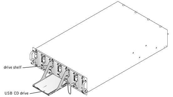
- Attach the drive shelf to the front of the system (see Figure 1-3).
Ensure that the drive shelf rests on the center handles of the server modules. If it is placed in the center, you can attach one of the USB drives to any server module.
Figure 1-3. Attaching the Drive Shelf
 |
NOTICE: The USB diskette or USB CD drive must be placed on the drive shelf during
operation. The drive must be horizontal and level to operate properly.
|
- Place the drive on the shelf and attach the drive to the server module that you want to
configure.
 |
NOTE: If the drive must be designated as the boot drive, reset the power on the server
module.
|
- Remove the drive and the drive shelf. Do not leave the drive attached during normal
system operation.
The back of the system provides access to the network switch modules (2), the system management module, the fans, and power supplies (see Figure 1-4). Table 1-2 provides information about the back-panel features.
Figure 1-4. Back-Panel Features
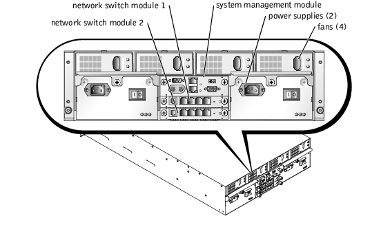
Table 1-2. Back-Panel Features
|
Component
|
Description
|
|---|
Power supply indicators | Provide information about power status (see "Power-Supply Indicator Codes"). |
Network switch module indicators | Provide information about the 10/100/100 BASE-T network status (see "Network Switch Module Features"). |
System management module indicators | Provide information about system status, system management status, and port status. |
Each hot-pluggable power supply has indicators that can provide information about power status, fault, and the presence of AC power (see Figure 1-5). Table 1-3 lists the power-supply indicator codes.
Figure 1-5. Power-Supply Indicators
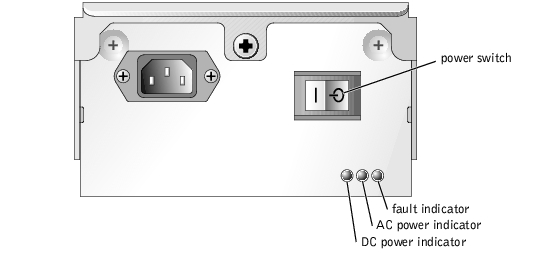
Table 1-3. Power-Supply Indicator Codes
|
Indicator
|
Activity Indicator
|
Indicator Code
|
|---|
DC power indicator | Green | Indicates that the power supply is operational. |
AC power present indicator | Green | Indicates that AC power is present at the power supply and that the system is connected to an AC power source. |
Fault indicator | Amber | Indicates that the power supply is in a fault condition. See your system Installation and Troubleshooting Guide for more information. |
Each system can accommodate up to two network switch modules. The network switch modules provide information about network activity and link status and a system fault indicator (see Figure 1-6). The switch also provides an external RJ11 connection to a serial null modem cable used for switch setup and configuration. The RJ11 is not used during normal system operation. Table 1-4 provides details about the operation of the indicators.
 |
NOTE: Do not connect the configuration port to a data or telephone network.
|
Figure 1-6. Network Switch Module Indicators and Features
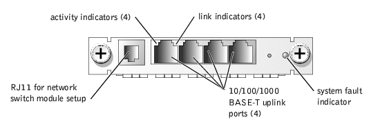
Table 1-4. Network Switch Module Indicator Codes
|
Indicator Type
|
Activity
Indicator
|
Indicator Code
|
|---|
Network indicator | Green | The port is connected to a valid link partner on the network. |
| Blinking | Network data is being sent or received. |
System fault indicator | Green | Indicates normal system operation. |
| Amber | Indicates a system power fault. See your system Installation and Troubleshooting Guide for more information. |
The system management module provides:
- Keyboard/mouse/video access to each server module
- Serial and Ethernet management ports
- An analog rack interface port to attach to an optional external KVM over IP switch
 |
NOTE: Connect the analog rack interface port only to an external KVM over IP switch
provided by Dell.
|
- Status indicators for the system management module and for the link to the system's onboard network switch module.
In addition, a system status connector allows you to attach the system status cable so that you can monitor system status after the system is mounted in a rack (see Figure 1-7). Table 1-5 provides information about the status indicators.
Figure 1-7. System Management Module Features
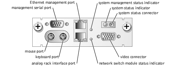
Table 1-5. System Management Module Indicators
|
Indicator Type
|
Activity
Indicator
|
Indicator Code
|
|---|
System status indicator | Blue | System is operating normally. |
| Amber | A system fault is present. See your system Installation and Troubleshooting Guide for more information. |
System management status indicator | Green | System management module is operating normally. |
| Amber | Indicates a system management module fault. See your system Installation and Troubleshooting Guide for more information. |
Network switch module status indicator | Green | Indicates that the system management module and the onboard network switch module are communicating. |
Ethernet management port | Off | The ERA/MC is not connected to the network. |
| Green | The ERA/MC is connected to a valid link partner on the network. |
| Blinking | Data is being sent or received. |
Analog rack interface port | Off | The KVM switch is not connected to an external KVM over IP switch. |
| Green | The KVM switch is connected to a valid external KVM over IP switch. |
| Blinking | Data is being sent or received. |
The system has four hot-pluggable system fans. Each fan has two indicators. Figure 1-8 shows a fan. Table 1-6 shows the fan indicator codes.
Figure 1-8. System Fan

Table 1-6. Fan Indicators
|
Indicator Type
|
Activity
Indicator
|
Indicator Code
|
|---|
Status indicator | Green | Fan is receiving power. |
Fault indicator | Amber | Fan is in fault condition. See your Installation and Troubleshooting Guide for additional information. |
- Support for up to six server modules. The system can support from one to six server modules. If less than six modules are installed in the system, a blank module is used. Blank modules are required for proper operation.
- System management module which provides access to systems management software features and the KVM switch.
- To access system management features, connect the null modem cable between the management port and an external PC. You may also obtain system management information through a Web browser connected to the RJ45 management port. Systems management software monitors the system and server module status.
- The system management module includes keyboard, video, and mouse connectors. The onboard KVM switch provides an onscreen display to select a server module.
- Embedded systems management circuitry that monitors operation of the system fans, and critical system voltages and temperatures. The systems management circuitry works in conjunction with your systems management software.
- Support for up to two network switch modules. Externally, each switch has four 10/100/1000 BASE-T Ethernet ports.
- Four hot-pluggable system fans.
- Two 1048-watt, hot-pluggable, redundant power supplies. The system can operate without power redundancy with six server modules and only one power supply turned on.
- One or two Intel® Pentium® III microprocessors with an internal operating speed of at least 1.26 GHz, a 512 KB cache, and a front-side (external) bus speed of 133 MHz.
- A minimum of 128 MB of system memory, upgradable to a maximum of 2 GB by installing PCI 133 registered, SDRAM memory modules in the two memory module sockets on the system board.
- Support for up to two 1-inch, internal Ultra3 SCSI hard drives.
- Integrated internal drive mirroring allows two SCSI disks to be mirrored through the integrated RAID controller.
- An external USB port to support either a 1.44-MB, 3.5-inch diskette drive or a USB CD drive. When either the diskette or USB CD drive is attached to the server module during boot, the drive is designated as the first boot drive. This designation allows you to install software on the server module's hard drives.
- An integrated VGA-compatible video subsystem with an ATI RAGE XL video controller. This video subsystem contains 8 MB of SDRAM video memory (nonupgradable). Maximum resolution is 1600 x 1200 x 16.7 million colors (noninterlaced).
For more information about specific features, see "Technical Specifications" and "Other Documents You May Need."
- A System Setup program for quickly viewing and changing system configuration information. For more information about this program, see "Using the System Setup Program."
- Enhanced security features, including a system password and a setup password, available through the System Setup program.
- System diagnostics for evaluating system components and devices. For information about using diagnostics, see "Running System Diagnostics" in your Installation and Troubleshooting Guide.
- Video drivers for displaying many application programs in high-resolution modes. For more information about drivers, see "Using the Dell OpenManage Server Assistant CD."
- Systems management software and documentation. Systems management software is used to manage and monitor each individual server module as well as the system as a whole including all of the server modules, network switch modules, power supplies, and fans. Systems management software manages the system locally and remotely on a network. Dell recommends that you use the systems management software provided with this system.
- Optional solutions software for Web hosting, caching, or load balancing. See your solutions software documentation for more information.
- Microsoft® Windows® 2000 Server and Advanced Server
- Windows.NET Server family
- Red Hat Linux Professional 7.3
Certain devices protect your system from the effects of problems such as power surges and power failures.
- PDU — Uses circuit breakers to ensure that the AC current load does not exceed the PDU's rating.
- Surge protector — Prevents voltage spikes, such as those that may occur during an electrical storm, from entering the system through the electrical outlet. They do not protect against brownouts, which occur when the voltage drops more than 20 percent below the normal AC line voltage level.
- Line conditioner — Maintains a system's AC power source voltage at a moderately constant level and provides protection from brownouts, but does not protect against a complete power loss.
- UPS — Uses battery power to keep the system running when AC power is unavailable. The battery is charged by AC power while it is available so that after AC power is lost, the battery can provide power to the system for a limited amount of time—from 15 minutes to approximately an hour. A UPS that provides only 5 minutes of battery power allows you to shutdown the system. Use surge protectors and PDUs with all universal power supplies, and ensure that the UPS is UL-safety approved.

|
The System Information Guide provides important safety and regulatory information. Warranty information may be included within this document or as a separate document. |
- The Rack Installation Guide included with your rack solution describes how to install your system into a rack.
- The Setting Up Your System document provides an overview of initially setting up your system.
- The Installation and Troubleshooting Guide describes how to troubleshoot the system and install or replace system components.
- Systems management software documentation describes the features, requirements, installation, and basic operation of the software.
- Operating system documentation describes how to install (if necessary), configure, and use the operating system software.
- Other documentation included on the CDs that came with your system describing the use of advanced system features.
- Documentation for any components you purchased separately provides information to configure and install these options.
- Updates are sometimes included with the system to describe changes to the system, software, and/or documentation.
 |
NOTE: Always read the updates first because they often supersede information in other
documents.
|
- Release notes or readme files may be included to provide last-minute updates to the system or documentation, or advanced technical reference material intended for experienced users or technicians.
If you do not understand a procedure in this guide or if the system does not perform as expected, see your Installation and Troubleshooting Guide.
Dell Enterprise Training and Certification is available; see www.dell.com/training for more information. This service may not be offered in all locations.
Back to Contents Page
 Server Module Status Features
 Obtaining Technical Assistance


