Back to Contents Page
Troubleshooting:
Dell™ PowerEdge™ 1655MC Integrated Switch User's Guide
 Diagnosing
Switch Indicators
 Diagnosing
Port Connections
 Management
Access
 Using
System Logs
 Management
VLAN Access
The following sections discuss troubleshooting associated with the LEDs:
- All LEDs are off. Check the following:
- Ensure that you are using RJ-45 cable for all network connections and
not RJ-11 (telephone) cable.
- Ensure that power is supplied to the server chassis.
| |
 |
NOTE: Operating temperature for the switch must not exceed
40 ºC. The server chassis should not be placed in the direct sunlight
or near warm air exhausts or heaters. |
- Link LED is OFF. Check the following:
- Verify that the chassis and attached device are powered on.
- Be sure the cable is plugged into both the switch and corresponding
device.
- Verify that the proper cable type is used and its length does not exceed
specified limits.
- Check the attached device and cable connections for possible defects.
Replace the defective adapter or cable if necessary.
The following section discusses troubleshooting associated with ports:
- A port does not work. Check the following:
- The cable connections are secure and the cables are connected to the
correct ports at both ends of the link.
- The port status (Admin) is enabled, and the auto-negotiation feature
is enabled. See the Port Configuration page
for more information.
You can access the management agent in the switch from anywhere within the
attached network using Telnet, a Web browser, or other SNMP-based systems management
software. The following sections discuss troubleshooting related to management
access to the switch:
- The terminal cannot access the switch. Check the following:
- Your terminal is correctly configured to operate as a VT100 terminal.
- You are using a proper cable.
- Use a null-modem cable to connect to the DB-9 port on the remote
access module.
- Or use the DB-9-to-RJ-11 cable to connect to the serial port on
the switch.
- Be sure to have set the terminal emulator program to VT100 compatible,
8 data bits, 1 stop bit, no parity and 9600 bps. See Required
Connections for more information.
- You cannot access the switch using Telnet. Check the following:
- Be sure to have configured the switch’s management VLAN with a
valid IP address, subnet mask and default gateway.
- Be sure your management station has management VLAN access (see Management
VLAN Access).
- The chassis is powered-up.
- Check that you have a valid network connection to the switch and that
the port you are using has not been disabled.
- You may have exceeded four concurrent Telnet sessions. Try connecting
again at a later time.
- The Web browser cannot access the switch. Check the following:
- Be sure to have configured the switch’s management VLAN with a
valid IP address, subnet mask and default gateway.
- Be sure your management station has management VLAN access (see Management
VLAN Access).
- The chassis is powered-up.
- Check that you have a valid network connection to the switch and that
the port you are using has not been disabled.
- SNMP management software cannot access the switch. Check the following:
- Be sure to have configured the switch’s management VLAN with a
valid IP address, subnet mask and default gateway.
- Be sure your management station has management VLAN access (see Management
VLAN Access).
- SNMP is enabled on the switch and community strings have been set with
the appropriate access rights.
- The chassis is powered-up.
- Check that you have a valid network connection to the switch and that
the port you are using has not been disabled.
Using System Logs
If a fault does occur, refer to the other manuals for the server chassis to
ensure that the problem you encountered is actually caused by the switch. If
this is true, then follow the steps described below.
- Enable logging.
- Set the error messages reported to include all categories.
- Designate the SNMP host that will receive the error messages.
- Repeat the sequence of commands or other actions that lead up to the error.
- Make a list of the commands or circumstances that led to the fault. Also
make a list of any error messages displayed.
- Contact customer service.
Example
|
(config)#logging on
(config)#logging history flash 7
(config)#snmp-server host 10.1.0.23
.
.
.
|
Management VLAN Access
The following sections discuss troubleshooting related to management VLAN access
to the switch.
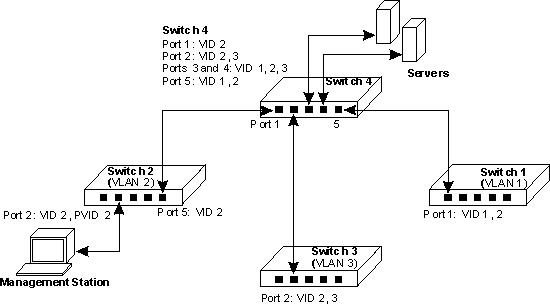
Layer 2 Switch Connections
If you are having problems setting up management access in a network where
there are only Layer 2 switch connections to the management station, consider
the following example.
Three switches, which form three VLANs, are interconnected to a fourth core
switch. Network administrators connected to one switch need to be able to access
all switches for management. The VLAN port memberships should be set up as illustrated
in the diagram below.

In this diagram the management VLAN is VID 2 and all inter-switch ports are
configured as tagged ports. It is important that the ports interconnecting the
switches are configured as members of the management VLAN and that the management
station is connected to a port that is also a member of this VLAN.
For management VLAN access, be sure to always check the following:
- Be sure to have configured the switch’s management VLAN with a valid
IP address and subnet mask.
- That the management station has an IP address in the same subnet as the
management VLAN.
- That the management station is connected to a switch port that is a member
of the management VLAN.
- That ports interconnecting switches in the network are tagged ports and
are a member of the management VLAN.
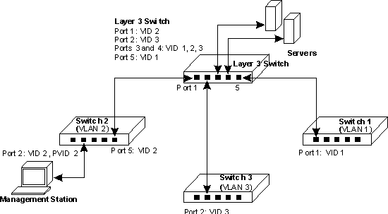
Layer 3 Switch Connections
If you are having problems setting up management access in a network where
there are Layer 3 switch connections to the management station, consider the
following example.
Three Layer 2 switches, which form three VLANs, are interconnected to a fourth
Layer 3 switch. Network administrators connected to one Layer 2 switch need
to be able to access all switches for management. The VLAN port memberships
should be set up as illustrated in the diagram below.

In this diagram the management VLAN is different on each switch, with the Layer
3 switch interconnecting the VLANs. All ports are configured as tagged ports.
It is important that the ports on the Layer 3 switch that connect to the other
switches are configured as members of the management VLAN for each switch.
For management VLAN access, be sure to always check the following:
- Be sure to have configured the switch’s management VLAN with a valid
IP address, subnet mask and default gateway.
- That the management station has valid IP address, subnet mask and default
gateway.
- That the management station is connected to a switch port that is a member
of the management VLAN.
- That ports interconnecting switches and the Layer 3 switch in the network
are tagged ports and are a member of the management VLAN.
Back to Contents Page

