| CAUTION: DO NOT plug a phone jack connector into any RJ-45 port. Use only twisted-pair cables with RJ-45 connectors that conform with FCC standards. |
1000BASE-T ports switch support automatic MDI/MDI-X operation, so you can use straight-through cables for all network connections to servers or other switches. However, remember that auto-negotiation must be enabled for automatic MDI/MDI-X pinout configuration to function properly. (See the Port Configuration page.)
The table below shows the 1000BASE-T MDI and MDI-X port pinouts. These ports require that all four pairs of wires be connected. Note that for 1000BASE-T operation, all four pairs of wires are used for both transmit and receive.
Use 100-ohm Category 5 or 5e unshielded twisted-pair (UTP) or shielded twisted-pair (STP) cable for 1000BASE-T connections, with RJ-45 connectors on both ends. Also be sure that the length of any twisted-pair connection does not exceed 100 meters (328 feet).
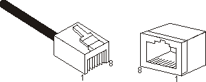
Figure 1. RJ-45 Connector Pin Numbers

Table 1 . 1000BASE-T Pin Assignments
| Pin |
MDI Signal Name | MDI-X Signal Name |
| 1 | Transmit Data plus (TD1+) | Transmit Data plus (TD2 +) |
| 2 | Receive Data minus (RD1-) | Receive Data minus (RD2-) |
| 3 | Transmit Data plus (TD2+) | Transmit Data plus (TD1+) |
| 4 | Transmit Data plus (TD3+) | Transmit Data plus (TD4+) |
| 5 | Receive Data minus (RD3-) | Receive Data minus (RD4-) |
| 6 | Receive Data minus (RD2-) | Receive Data minus (RD1-) |
| 7 | Transmit Data plus (TD4+) | Transmit Data plus (TD3+) |
| 8 | Receive Data minus (RD4-) | Receive Data minus (RD3-) |
All Category 5 UTP cables that are used for 100BASE-TX connections should also work for 1000BASE-T, providing that all four wire pairs are connected. However, it is recommended that for all critical connections, or any new cable installations, Category 5e (enhanced Category 5) cable should be used. The Category 5e specification includes test parameters that are only recommendations for Category 5. Therefore, the first step in preparing existing Category 5 cabling for running 1000BASE-T is a simple test of the cable installation to be sure that it complies with the IEEE 802.3ab standards.
Installed Category 5 cabling must pass tests for Attenuation, Near-End Crosstalk (NEXT), and Far-End Crosstalk (FEXT). This cable testing information is specified in the ANSI/TIA/EIA-TSB-67 standard. Additionally, cables must also pass test parameters for Return Loss and Equal-Level Far-End Crosstalk (ELFEXT). These tests are specified in the ANSI/TIA/EIA-TSB-95 Bulletin, “The Additional Transmission Performance Guidelines for 100 Ohm 4-Pair Category 5 Cabling."
| NOTE: When testing your cable installation, be sure to include all patch cables between switches and end devices. |
If your existing Category 5 installation does not meet one of the test parameters for 1000BASE-T, there are basically three measures that can be applied to try to correct the problem:
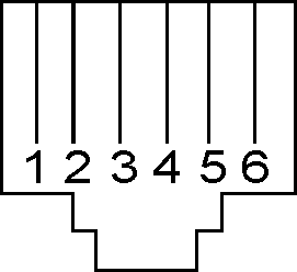
The RJ-11 port on the switch is used for console configuration. The switch includes a DB-9-to-RJ-11 cable. Attach the DB-9 connector of this cable into the console port on your terminal or computer, and the RJ-11 jack on the other end of the cable into the console port on the switch. The on-board menu-driven configuration program can be accessed from a terminal, or a system running a terminal emulation program. The pin assignments used on the RJ-11 port and cable adapter are provided in the following table.
Figure 2. Console Port Pin Numbers

Table 1. Console Port Pin Assignments
| EIA Circuit |
CCITT Signal | Description |
Pin #
|
|
|
RJ-11 Port |
DB-9 Port | |||
| BB | 104 | RxD (Received Data) | 5 | 2 |
| BA | 103 | TxD (Transmitted Data) | 2 | 3 |
| CA | 105 | RTS (Request-to-Send) | 6 | 7 |
| CB | 106 | CTS (Clear-to-Send) | 1 | 8 |
Table 2. Adapter Cable Pin Assignments
|
Description |
Pin #
|
|
|
RJ-11 Jack |
DB-9 Jack | |
| RxD - TxD | 5 (RxD) | 3 (TxD) |
| TxD - RxD | 2 (TxD) | 2 (RxD) |
| RTS - CTS | 6 (RTS) | 8 (CTS) |
| CTS - RTS | 1 (CTS) | 7 (RTS) |