Overview
Starting the Test Utility
View Adapter Configuration
Test Adapter menu
Display Diagnostic Log
Intel's diagnostic software lets you test the adapter to see if there are any problems with the adapter hardware, the cabling, or the network connection. You can also use diagnostics to isolate problems during troubleshooting. DIAGS.EXE runs under MS-DOS* v6.22 or later. It will not run from a DOS window in Windows*.
This utility is designed to test hardware operation and confirm the adapter's ability to communicate with another adapter in the same network, primarily confirming cabling. It is not a throughput measurement tool.
DIAGS.EXE can test the adapter whether or not there is a responder on the network. In order to do a thorough test, however, you should set up a second system on the network as a responder prior to starting a test.
| NOTE: If there is a DOS network driver present, such as NDIS2 or DOS-ODI, the test utility and/or the network driver could become unstable. You should reboot and ensure that there are no network drivers loaded. |
DIAGS, and press <Enter>.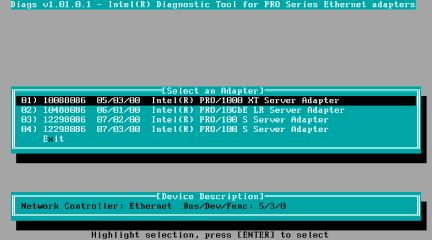
Selecting View Adapter Configuration will bring up the adapter configuration screen. This screen describes various properties of the adapter.
Press <F5> to view additional information on the PCI slot occupied by the adapter. This is primarily used for troubleshooting by Customer Support.
Press <Enter> to return to the main menu.
Selecting Test Adapter from the Main Menu brings up the Test Menu. This menu allows the user to test the adapter, select which tests to perform, set the adapter up as a network responder, or perform a continuous network sender test.
Selecting this option brings up the test screen. While tests are being performed, a rotating spinner is shown to indicate the application is still "alive." The results of the tests are displayed as each test is performed. If multiple test passes are selected, the results contain a count of test failures. A list containing zeros means that all tests have passed.
If there is no responder on the network, the Network Test will indicate a failure. To correct this situation, set up a system on the network to act as a responder, and re-run the test.
The test setup screen allows you to configure and select the specific tests desired. Each option is toggled by moving the cursor with the arrow keys and pressing <Enter> to change the option. The number of tests is simply entered from the keyboard in the appropriate box.
| NOTE: The test program will test attributes that are applicable to your adapter. Only supported tests are displayed. The screen shown here is an example of the types of tests performed. |
Diagnostic Log - This is normally disabled. If enabled, the program will ask asks for a directory for the log file. The file it places here is named DIAG.LOG.
Device Registers - Test patterns are written, read, and verified through the adapter's device registers to ensure proper functionality.
FIFOs - This will write test bit patterns to the adapter's FIFO buffers, to make sure the FIFOs are working properly.
EEPROM - This test tests both the readability of the EEPROM as well as the integrity of the data stored in the EEPROM. It reads the EEPROM and calculates the checksum. This checksum is then compared to the checksum stored in the EEPROM. If values are not the same, the test reports failure.
Interrupt - This tests the adapter's ability to generate an interrupt and have it propagated through the system to the Programmable Interrupt Controller (PIC). The test triggers an interrupt by setting the interrupt cause register and then verifies that an interrupt has been triggered.
MAC Loopback and Phy Loopback - There are two internal loopback tests. These tests set the adapter in the appropriate loopback mode and send packets back through the adapter's receive circuitry and logic.
Link - This checks to see if the adapter has link or does not have link.
Network Test - The Network Test looks for a responder, and then sends packets. If no responder is found, the test reports failure. If packets are received back from the responder, the test reports success.
This allows the user to setup the adapter as a responder so another system can perform the continuous network test. Selecting this option brings up the transmit/receive screen. This will fail if the adapter does not have link.
Although you can use a variety of adapters as the responder, and either connect directly (with a crossover cable) or through a switch, ideal results are obtained with a same-type adapter.
When you press <Esc>, the responder operation is canceled and control is immediately returned to the Test Adapter menu.
This tests to make sure that the network is working properly. The adapter will look for a responder. If none is found, the program will tell you. The transmit/receive screen appears just as with the
Setup As Responder menu option.
When this test is running, the following information is displayed and continuously updated:
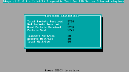
When you press <Esc>, this test is canceled and control is returned to the Test Adapter menu.
When the diagnostic log is enabled, test results are recorded in a log file named "diags.log". If it does not already exist, the test utility creates it; otherwise new data is appended to it. This command displays the contents of the log file for your convenience.
Each entry in the log file is time stamped. The test run banner identifies the tested adapter according to
its bus slot address.
Please read all restrictions and disclaimers.