Back to Contents Page

CIM_LogicalElement

Dell OpenManage™ Server Administrator CIM Reference Guide

  CIM_LogicalElement

  CIM_System

  CIM_ComputerSystem

  DELL_System

  CIM_LogicalDevice

  CIM_Sensor

  CIM_NumericSensor

  CIM_TemperatureSensor

  CIM_CurrentSensor

  CIM_VoltageSensor

  CIM_Tachometer

  CIM_WatchDog

  CIM_CoolingDevice

  CIM_Fan

  CIM_UserDevice

  CIM_PointingDevice

  CIM_Keyboard

  CIM_PowerSupply

  CIM_Controller

  CIM_ParallelController

  CIM_SerialController

  CIM_PCIController

  CIM_PCIDevice

  CIM_PCIBridge

  CIM_Processor

  CIM_StorageExtent

  CIM_Memory

  CIM_CacheMemory

  CIM_SoftwareElement

  CIM_BIOSElement

  CIM_SoftwareFeature

  DELL_SoftwareFeature

  CIM_SystemResource

  CIM_IRQ

  CIM_MemoryMappedIO

  CIM_DMA

  CIM_RedundancyGroup

  CIM_ExtraCapacityGroup

  DELL_PSRedundancyGroup

  DELL_FanRedundancyGroup


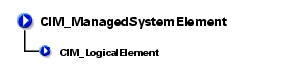
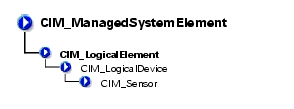
CIM_LogicalElement is a CIM-defined class containing the subclasses shown in Figure 3-1.

Figure 3-1. CIM_LogicalElement Class Structure

CIM_ManagedSystemElement

CIM_LogicalElement

CIM_System

CIM_ComputerSystem

Dell_System

CIM_LogicalDevice

CIM_Sensor

CIM_NumericSensor

CIM_TemperatureSensor

CIM_CurrentSensor

CIM_VoltageSensor

CIM_Tachometer

CIM_Watchdog

CIM_CoolingDevice

CIM_Fan

CIM_UserDevice

CIM_PointingDevice

CIM_Keyboard

CIM_PowerSupply

CIM_Controller

CIM_ParallelController

CIM_SerialController

CIM_PCIController

CIM_PCIDevice

CIM_PCIBridge

CIM_Processor

CIM_StorageExtent

CIM_Memory

CIM_CacheMemory

CIM_SoftwareElement

CIM_BIOSElement

CIM_SoftwareFeature

Dell_SoftwareFeature

CIM_SystemResource

CIM_IRQ

CIM_MemoryMappedIO

CIM_DMA

CIM_RedundancyGroup

CIM_ExtraCapacityGroup

DELL_PSRedundancyGroup

DELL_FanRedundancyGroup


CIM_LogicalElement

The Distributed Management Task Force (DMTF) identified in Table 3-1 lists the following characteristics for members of the CIM_LogicalElement class:

Table 3-1. CIM_LogicalElement Properties 

Class Name:

CIM_LogicalElement

Parent Class:

CIM_ManagedSystemElement


CIM_System

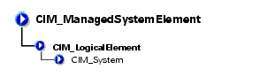
The CIM_System class shown in Table 3-2 defines a collection of managed system elements that operates as a functional whole. An instance of the CIM_System class contains a well-defined list of components that work together to perform a specific function.

Table 3-2. CIM_System Properties 

Class Name:

CIM_System

Parent Class:

CIM_LogicalElement

Property

Description

Data Type

CreationClassName

See Table 1-2, "Common Properties of Classes."

string

Name

Indicates the name of a specific system, such as a particular storage system or server.

string

PrimaryOwnerContact

Provides information on how the primary system owner can be reached, for example, a phone number or e-mail address.

string

PrimaryOwnerName

Indicates the name of the primary system owner.

string

Roles

An array of strings that specifies the roles this system plays in the IT environment. For example, for an instance of a network system, the Roles property might contain the string "storage system."

string


CIM_ComputerSystem

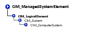
The CIM_ComputerSystem class listed in Table 3-3 contains some or all of the following CIM_ManagedSystemElements: file system, operating system, processor and memory (volatile and/or nonvolatile storage). For properties, see Table 3-2, "CIM_System Properties."

Table 3-3. CIM_ComputerSystem Properties 

Class Name:

CIM_ComputerSystem

Parent Class:

CIM_System


DELL_System

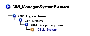
The DELL_System class listed in Table 3-4 is the set of all Dell™ instrumented systems, including server and storage systems. For properties, see Table 3-2, "CIM_System Properties."

Table 3-4. DELL_System Properties 

Class Name:

DELL_System

Parent Class:

CIM_ComputerSystem


CIM_LogicalDevice

The CIM_LogicalDevice class described in Table 3-5 models a hardware entity that may be realized in physical hardware. CIM_LogicalDevice includes any characteristics of a logical device that manages its operation or configuration. An example of a logical device is a temperature sensor's reading of actual temperature.

Table 3-5. CIM_Logical Device Properties 

Class Name:

CIM_LogicalDevice

Parent Class:

CIM_LogicalElement

Property

Description

Data Type

SystemCreationClassName

See Table 1-2, "Common Properties of Classes."

string

SystemName

Indicates the scoping system's name.

string

CreationClassName

See Table 1-2, "Common Properties of Classes."

string

DeviceID

Identifies an address or other identifying information to uniquely name the logical device.

string


CIM_Sensor

The CIM_Sensor class explained in Table 3-6 contains hardware devices capable of measuring the characteristics of some physical property, for example, the temperature or voltage characteristics of a computer system.

Table 3-6. CIM_Sensor Properties 

Class Name:

CIM_Sensor

Parent Class:

CIM_LogicalDevice

Property

Description

Data Type

SensorType

The type of the sensor, for example, voltage or temperature sensor.

Values for the SensorType property are as follows:

  1. Unknown
  2. Other
  3. Temperature sensors measure the environmental temperature.
  4. Voltage sensors measure electrical voltage.
  5. Current sensors measure current readings.
  6. Tachometers measure speed/revolutions of a device. For example, a fan device can have an associated tachometer that measures its speed.

uint16


CIM_NumericSensor

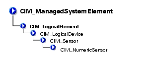
The CIM_NumericSensor class described in Table 3-7 returns numerical settings and may also support threshold settings. Figure 3-2 shows the relationship among upper and lower critical and upper and lower noncritical threshold values. The normal range falls between upper and lower noncritical thresholds.

Figure 3-2. Ranges for Threshold Values

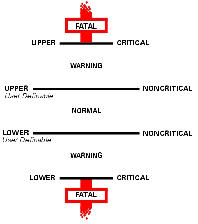
Table 3-7 provides definitions for NumericSensor properties.

Table 3-7. CIM_NumericSensor Properties 

Class Name:

CIM_NumericSensor

Parent Class:

CIM_Sensor

Property

Description

Data Type

UnitModifier

See Table 1-2, "Common Properties of Classes."

sint32

CurrentReading

See Table 1-2, "Common Properties of Classes."

sint32

IsLinear

See Table 1-2, "Common Properties of Classes."

Boolean

LowerThresholdNonCritical

See Table 1-2, "Common Properties of Classes."

sint32

UpperThresholdNonCritical

See Table 1-2, "Common Properties of Classes."

sint32

LowerThresholdCritical

See Table 1-2, "Common Properties of Classes."

sint32

UpperThresholdCritical

See Table 1-2, "Common Properties of Classes."

sint32

SupportedThresholds

An array representing the thresholds supported by this sensor. The supported values are as follows:

  1. LowerThresholdNonCritical
  2. UpperThresholdNonCritical
  3. LowerThresholdCritical
  4. UpperThresholdCritical

uint16

EnabledThresholds

An array representing the thresholds that are currently enabled for this sensor.

Enabled threshold values are as follows:

  1. LowerThresholdNonCritical
  2. UpperThresholdNonCritical
  3. LowerThresholdCritical
  4. UpperThresholdCritical

uint16

SettableThresholds

An array representing the writable thresholds supported by sensor.

Settable threshold values are as follows:

  1. LowerThresholdNonCritical
  2. UpperThresholdNonCritical

uint16


CIM_TemperatureSensor

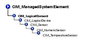
The CIM_TemperatureSensor class listed in Table 3-8 contains sensors that sample ambient temperature and return a value in degrees Celsius.

Table 3-8. CIM_TemperatureSensor Properties 

Class Name:

CIM_TemperatureSensor

Parent Class:

CIM_NumericSensor

Property

Description

Data Type

UnitModifier

See Table 1-2, "Common Properties of Classes."

sint32

CurrentReading

See Table 1-2, "Common Properties of Classes."

sint32

IsLinear

See Table 1-2, "Common Properties of Classes."

Boolean

LowerThresholdNonCritical

See Table 1-2, "Common Properties of Classes."

sint32

UpperThresholdNonCritical

See Table 1-2, "Common Properties of Classes."

sint32

LowerThresholdCritical

See Table 1-2, "Common Properties of Classes."

sint32

UpperThresholdCritical

See Table 1-2, "Common Properties of Classes."

sint32


CIM_CurrentSensor

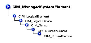
The CIM_CurrentSensor class listed in Table 3-9 contains sensors that measure amperage and returns a value in amperes.

Table 3-9. CIM_CurrentSensor Properties 

Class Name:

CIM_CurrentSensor

Parent Class:

CIM_NumericSensor

Property

Description

Data Type

UnitModifier

See Table 1-2, "Common Properties of Classes."

sint32

CurrentReading

See Table 1-2, "Common Properties of Classes."

sint32

IsLinear

See Table 1-2, "Common Properties of Classes."

Boolean

LowerThresholdNonCritical

See Table 1-2, "Common Properties of Classes."

sint32

UpperThresholdNonCritical

See Table 1-2, "Common Properties of Classes."

sint32

LowerThresholdCritical

See Table 1-2, "Common Properties of Classes."

sint32

UpperThresholdCritical

See Table 1-2, "Common Properties of Classes."

sint32


CIM_VoltageSensor

The CIM_VoltageSensor class shown in Table 3-10 contains sensors that measure voltage and return a value in volts.

Table 3-10. CIM_VoltageSensor Properties 

Class Name:

CIM_VoltageSensor

Parent Class:

CIM_NumericSensor

Property

Description

Data Type

UnitModifier

See Table 1-2, "Common Properties of Classes."

sint32

CurrentReading

See Table 1-2, "Common Properties of Classes."

sint32

IsLinear

See Table 1-2, "Common Properties of Classes."

Boolean

LowerThresholdNonCritical

See Table 1-2, "Common Properties of Classes."

sint32

UpperThresholdNonCritical

See Table 1-2, "Common Properties of Classes."

sint32

LowerThresholdCritical

See Table 1-2, "Common Properties of Classes."

sint32

UpperThresholdCritical

See Table 1-2, "Common Properties of Classes."

sint32


CIM_Tachometer

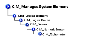
The CIM_Tachometer class listed in Table 3-11 contains devices that measure revolutions per minute (RPM) of a fan and return the value in RPMs.

Table 3-11. CIM_Tachometer Properties 

Class Name:

CIM_Tachometer

Parent Class:

CIM_NumericSensor

Property

Description

Data Type

SensorType

See Table 1-2, "Common Properties of Classes."

uint16

UnitModifier

See Table 1-2, "Common Properties of Classes."

sint32

CurrentReading

See Table 1-2, "Common Properties of Classes."

sint32

IsLinear

See Table 1-2, "Common Properties of Classes."

Boolean

LowerThresholdNonCritical

See Table 1-2, "Common Properties of Classes."

sint32

UpperThresholdNonCritical

See Table 1-2, "Common Properties of Classes."

sint32


CIM_WatchDog

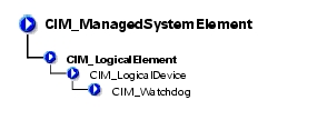
The CIM_WatchDog class described in Table 3-12 represents a timer that is implemented in system hardware. The watchdog feature allows the hardware to monitor the state of the operating system, BIOS, or a software component installed on the system. If the monitored component fails to rearm the timer before its expiration, the hardware assumes that the system is in a critical state and could reset the system. This feature can also be used as an application watchdog timer for a mission-critical application. In this case, the application would assume responsibility for rearming the timer before expiration.

Table 3-12. CIM_WatchDog Properties 

Class Name:

CIM_WatchDog

Parent Class:

CIM_LogicalDevice

Property

Description

Data Type

MonitoredEntity

Indicates the entity that is currently being monitored by the watchdog feature. This property is used to identify the module that is responsible for rearming the watchdog at periodic intervals. Values for the MonitoredEntity property are as follows:

  1. Unknown
  2. Other
  3. Operating System

uint16

MonitoredEntity Description

A string describing additional textual information about the monitored entity.

string

TimeoutInterval

Indicates the time-out interval used by the watchdog, in microseconds.

uint32

TimerResolution

Indicates the resolution of the watchdog timer. For example, if this value is 100, then the timer can expire anytime between –100 microseconds and +100 microseconds.

uint32


CIM_CoolingDevice

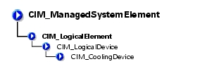
The CIM_CoolingDevice class described in Table 3-13 contains a set of devices that work to keep the ambient internal temperature of the system at a safe value.

Table 3-13. CIM_CoolingDevice Properties 

Class Name:

CIM_CoolingDevice

Parent Class:

CIM_LogicalDevice

Property

Description

Data Type

ActiveCooling

Specifies whether the device provides active (as opposed to passive) cooling.

Boolean


CIM_Fan

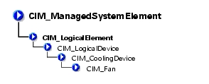
The CIM_Fan class explained in Table 3-14 contains a set of devices that work to keep the ambient internal temperature of the system at a safe value by circulating air.

Table 3-14. CIM_Fan Properties 

Class Name:

CIM_Fan

Parent Class:

CIM_CoolingDevice

Property

Description

Data Type

VariableSpeed

Specifies whether the fan supports variable speeds.

Boolean

DesiredSpeed

Indicates the currently requested fan speed, defined in RPM. When the value = TRUE, the fan supports variable speeds. When a variable speed fan is supported (VariableSpeed Boolean = TRUE), the actual speed is determined using a sensor (CIM_Tachometer) that is associated with the fan.

uint64


CIM_UserDevice

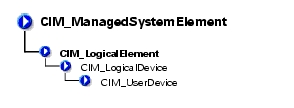
The CIM_UserDevice class shown in Table 3-15 contains logical devices that allow a computer system's users to input, view, or hear data. Classes derived from CIM_UserDevice include CIM_Keyboard and CIM_PointingDevice.

Table 3-15. CIM_UserDevice Properties 

Class Name:

CIM_UserDevice

Parent Class:

CIM_LogicalDevice

Property

Description

Data Type

IsLocked

Indicates whether the device is locked, preventing user input or output.

Boolean


CIM_PointingDevice

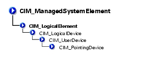
The CIM_PointingDevice class described in Table 3-16 includes those devices used to point to regions of a display. Examples are a mouse or a trackball.

Table 3-16. CIM_PointingDevice Properties 

Class Name:

CIM_PointingDevice

Parent Class:

CIM_UserDevice

Property

Description

Data Type

PointingType

Indicates the type of pointing device. Values for the PointingType property are as follows:

  1. Other
  2. Unknown
  3. Mouse
  4. Trackball
  5. Trackpoint
  6. Glidepoint
  7. Touch pad
  8. Touch screen
  9. Mouse—optical sensor

Boolean

NumberOfButtons

Indicates the number of buttons. If the CIM_PointingDevice has no buttons, a value of 0 is returned.

uint8

Handedness

Integer indicating whether the CIM_PointingDevice is configured for right- or left-handed operation. Values for the Handedness property are as follows:

  1. Unknown
  2. Not applicable
  3. Right-handed operation
  4. Left-handed operation

uint16


CIM_Keyboard

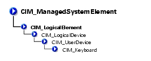
The CIM_Keyboard class explained in Table 3-17 includes devices that allow users to enter data.

Table 3-17. CIM_Keyboard Properties 

Class Name:

CIM_Keyboard

Parent Class:

CIM_UserDevice

Property

Description

Data Type

NumberOfFunctionKeys

Indicates the number of function keys on the keyboard.

uint16

Layout

A free-form string indicating the format and layout of the keyboard.

string

Password

An integer indicating whether a hardware-level password is enabled at the keyboard, preventing local input. Values for the Password property are as follows:

  1. Other
  2. Unknown
  3. Disabled
  4. Enabled
  5. Not implemented

uint16


CIM_PowerSupply

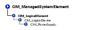
The CIM_PowerSupply class described in Table 3-18 contains devices that provide current and voltage for the operation of the system and its components.

Table 3-18. CIM_PowerSupply Properties 

Class Name:

CIM_PowerSupply

Parent Class:

CIM_LogicalDevice

Property

Description

Data Type

IsSwitchingSupply

Indicates that the power supply is a switching power supply and not a linear power supply.

Boolean

Range1InputVoltageLow

Indicates the low voltage in millivolts of input voltage range 1 for this power supply. A value of 0 denotes unknown.

uint32

Range1InputVoltageHigh

Indicates the high voltage in millivolts of input voltage range 1 for this power supply. A value of 0 denotes unknown.

uint32

ActiveInputVoltage

Indicates which input voltage range is currently in use. Range 1, 2, or both can be specified using the values 3, 4, or 5, respectively. If the supply is not drawing power, a value of 6 (neither) can be specified. This information is necessary in the case of an uninterruptible power supply (UPS), a subclass of power supply. Values for the ActiveInputVoltage property are as follows:

  1. Other
  2. Unknown
  3. Range 1
  4. Range 2
  5. Both range 1 and range 2
  6. Neither range 1 nor range 2

uint16

TotalOutputPower

Represents the total output power of the power supply in milliwatts. A value of 0 denotes that the power output is unknown.

uint32


CIM_Controller

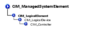
The CIM_Controller class shown in Table 3-19 groups miscellaneous control-related devices. Examples of controllers are small computer system interface (SCSI) controllers, Universal Serial Bus (USB) controllers, and serial controllers.

Table 3-19. CIM_Controller Properties 

Class Name:

CIM_Controller

Parent Class:

CIM_LogicalDevice

Property

Description

Data Type

ProtocolSupported

The protocol used by the controller to access controlled devices. Values for the ProtocolSupported property are as follows:

  1. Other
  2. Unknown
  3. PCI
  4. Parallel protocol

uint16


CIM_ParallelController

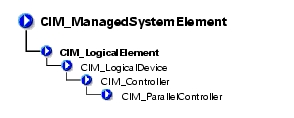
The CIM_ParallelController class identified in Table 3-20 contains a set of objects that control parallel devices. Parallel controllers transfer 8 or 16 bits of data at a time to the devices they control, for example, a parallel port controlling a printer.

Table 3-20. CIM_ParallelController Properties 

Class Name:

CIM_ParallelController

Parent Class:

CIM_Controller

Property

Description

Data Type

DMASupport

Set to TRUE if the parallel controller supports DMA.

Boolean

Security

An enumeration indicating the operational security for the controller. Values for the Security property are as follows:

  1. Other
  2. Unknown
  3. None
  4. External interface locked out
  5. External interface enabled
  6. Boot bypass

uint16


CIM_SerialController

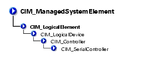
The CIM_SerialController class explained in Table 3-21 contains controllers that transfer data one bit at a time to the devices they control, for example, a serial port controlling a modem.

Table 3-21. CIM_SerialController Properties 

Class Name:

CIM_SerialController

Parent Class:

CIM_Controller

Property

Description

Data Type

MaxBaudRate

Indicates the maximum baud rate in bits per second supported by the serial controller.

uint32

Security

An enumeration indicating the operational security for the controller. Values for the Security property are as follows:

  1. Other
  2. Unknown
  3. None
  4. External interface locked out
  5. External interface enabled
  6. Boot bypass

uint16


CIM_PCIController

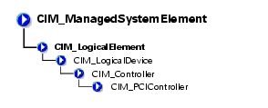
The CIM_PCIController class listed in Table 3-22 contains a set of devices that follow the Peripheral Component Interconnect (PCI) protocol defined by the Personal Computer Memory Card International Association (PCMCIA). The PCI protocol defines how data is transferred between devices. The CIM_PCIController class contains PCI adapters and bridges.

Table 3-22. CIM_PCIController Properties 

Class Name:

CIM_PCIController

Parent Class:

CIM_Controller

Property

Description

Data Type

CommandRegister

The current contents of the register that provides basic control over the device's ability to respond to, and/or perform PCI accesses. The data in the capabilities array is gathered from the PCI status register and the PCI capabilities list as defined in the PCI specification.

uint16


Values for the CommandRegister property are as follows:

  1. Unknown
  2. Other
  3. Supports 66 MHz
  4. Supports user-definable features
  5. Supports fast back-to-back transactions
  6. PCI-X capable
  7. PCI power management supported
  8. Message signaled interrupts supported
  9. Parity error recovery capable
  10. AGP supported
  11. Vital product data supported
  12. Provides slot identification
  13. Hot swap supported


CIM_PCIDevice

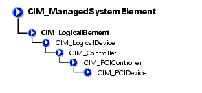
The CIM_PCIDevice class shown in Table 3-23 describes the capabilities and management of a PCI device controller on an adapter card.

Table 3-23. CIM_PCIDevice Properties 

Class Name:

CIM_PCIDevice

Parent Class:

CIM_PCIController

Property

Description

Data Type

BaseAddress

Identifies an array of up to six double-word base memory addresses.

uint32

SubsystemID

Identifies a subsystem identifier code.

uint16

SubsystemVendorID

Identifies a subsystem vendor ID. ID information is reported from a PCI device via protocol-specific requests. This information is also present in the CIM_PhysicalElement class (the manufacturer property) for hardware, and the CIM_Product class (the vendor property) for information related to product acquisition.

uint16

ExpansionROMBaseAddress

Identifies a double-word expansion ROM base memory address.

uint32


CIM_PCIBridge

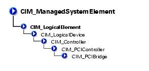
The CIM_PCIBridge class shown in Table 3-24 describes the capabilities and management of a PCI controller providing bridge-to-bridge capability. An example is a PCI to Industry-Standard Architecture (ISA) bus bridge.

Table 3-24. CIM_PCIBridge Properties 

Class Name:

CIM_PCIBridge

Parent Class:

CIM_PCIController

Property

Description

Data Type

BaseAddress

Identifies an array of double-word base memory addresses.

uint32

BridgeType

Indicates the type of bridge. A bridge is PCI to <value>, except for the Host, which is a host-to-PCI bridge. Values for the BridgeType property are as follows:

  1. Host
  2. ISA
  3. Other

uint16

BaseAddress

Identifies an array of double-word base memory addresses.

uint32


CIM_Processor

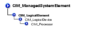
The CIM_Processor class described in Table 3-25 contains devices that interpret and execute demands, for example, the Intel® Xeon™ microprocessor.

Table 3-25. CIM_Processor Properties 

Class Name:

CIM_Processor

Parent Class:

CIM_LogicalDevice

Property

Description

Data Type

Role

A string describing the role of the microprocessor, for example, central microprocessor or math processor.

string

UpgradeMethod

Provides microprocessor socket information including data on how this microprocessor can be upgraded (if upgrades are supported). This property is an integer enumeration. Values for the UpgradeMethod property are as follows:

  1. Other
  2. Unknown
  3. Daughter board
  4. ZIF socket
  5. Replacement/piggy back
  6. None
  7. LIF socket
  8. Slot 1
  9. Slot 2
  10. 370-pin socket

uint16

MaxClockSpeed

Indicates the maximum speed (in MHz) of this microprocessor.

uint32

CurrentClockSpeed

Indicates the current speed (in MHz) of this microprocessor.

uint32

DataWidth

Indicates the processor data width in bits.

uint16

AddressWidth

Indicates the processor address width in bits.

uint16

Stepping

Indicates the revision level of the processor within the microprocessor family.

string

UniqueID

Identifies a globally unique identifier for the microprocessor. This identifier may only be unique within a microprocessor family.

string

CPUStatus

Indicates the current status of the microprocessor. For example, it may be disabled by the user via the BIOS or disabled due to a POST error. Values for the CPUStatus property are as follows:

  1. Unknown
  2. Microprocessor enabled
  3. Microprocessor disabled by user via BIOS setup
  4. Microprocessor disabled by BIOS (POST error)
  5. Microprocessor is idle
  6. Other

uint16

Family

Refers to the processor family type. Values for the Family property are as follows:

  1. Other
  2. Unknown
  3. Pentium® family
  4. Pentium PRO
  5. Pentium II
  6. Pentium MMX™
  7. Celeron®
  8. Xeon (Pentium II)
  9. Pentium III
  10. K5 family
  11. K6 family
  12. K6-2
  13. K6-3
  14. K7
  15. Xeon (Pentium III)
  16. i960™
  17. SH-3
  18. SH-4
  19. ARM
  20. StrongARM
  21. 6x86
  22. MediaGX
  23. MII
  24. WinChip
  25. DSP
  26. Video processor

uint16


CIM_StorageExtent

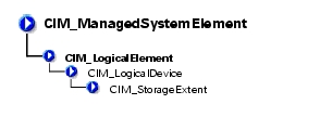
CIM_StorageExtent identified in Table 3-26 contains devices that manage data storage, for example, hard drives or microprocessor memory.

Table 3-26. CIM_StorageExtent Properties 

Class Name:

CIM_StorageExtent

Parent Class:

CIM_LogicalDevice


CIM_Memory

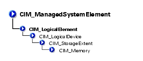
The CIM_Memory class identified in Table 3-27 describes the capabilities and management of storage extent devices, for example, cache memory or system memory.

Table 3-27. CIM_Memory Properties 

Class Name:

CIM_Memory

Parent Class:

CIM_StorageExtent


CIM_CacheMemory

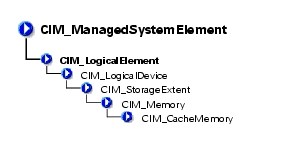
The CIM_CacheMemory class explained in Table 3-28 describes the capabilities and management of cache memory. Cache memory allows a microprocessor to access data and instructions faster than normal system memory.

Table 3-28. CIM_CacheMemory Properties 

Class Name:

CIM_CacheMemory

Parent Class:

CIM_Memory

Property

Description

Data Type

Level

Defines whether this is the primary, secondary, or tertiary cache. Values for the Level property are as follows:

  1. Other
  2. Unknown
  3. Primary
  4. Secondary
  5. Tertiary
  6. Not applicable

uint16

WritePolicy

Either defines whether this cache is a write-back or write-through cache or whether this information varies with address or is defined individually for each input/output (I/O). Values for the WritePolicy property are as follows:

  1. Other
  2. Unknown
  3. Write-back
  4. Write-through
  5. Varies with address
  6. Determination per I/O

uint16

CacheType

Defines whether this cache is for instruction caching, data caching, or both (unified). Values for the CacheType property are as follows:

  1. Other
  2. Unknown
  3. Instruction
  4. Data
  5. Unified

uint16

LineSize

Indicates the size, in bytes, of a single cache bucket or line.

uint32

ReadPolicy

Defines the policy used by the cache for handling read requests. Values for the ReadPolicy property are as follows:

  1. Other
  2. Unknown
  3. Read
  4. Read-ahead
  5. Read and read-ahead
  6. Determination per I/O

uint16


CIM_SoftwareElement

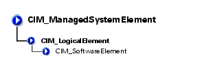
The CIM_SoftwareElement class described in Table 3-29 is used to define a CIM_SoftwareFeature. The CIM_SoftwareElement class consists of individually manageable or deployable parts for a particular platform. A software element's platform is uniquely identified by its underlying hardware architecture and operating system (for example, a system running Microsoft® Windows NT® on an Intel microprocessor). A software element's implementation on a particular platform depends on the platform's operating system.

Table 3-29. CIM_SoftwareElement Properties 

Class Name:

CIM_SoftwareElement

Parent Class:

CIM_LogicalElement

Property

Description

Data Type

Name

Indicates the name that identifies this software element.

string

Version

Provides the version in the form <major>.<minor>.<revision> or <major>.<minor><letter><revision>; for example, 1.2.3 or 1.2a3.

string

Manufacturer

See Table 1-2, "Common Properties of Classes."

string

BuildNumber

Indicates the internal identifier for this build of the software element.

string

IdentificationCode

Provides the manufacturer's identifier for this software element. Often this will be a stock keeping unit (SKU) or a part number.

string


CIM_BIOSElement

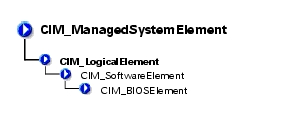
The CIM_BIOSElement class listed in Table 3-30 describes the BIOS for the system. The BIOS controls the following:

Table 3-30. CIM_BIOSElement Properties 

Class Name:

CIM_BIOSElement

Parent Class:

CIM_SoftwareElement

Property

Description

Data Type

Version

Provides the product version information.

string

Manufacturer

See Table 1-2, "Common Properties of Classes."

string

PrimaryBIOS

Specifies whether a given BIOS is the primary BIOS for the system. When the value = TRUE, the BIOS is the primary BIOS.

Boolean


CIM_SoftwareFeature

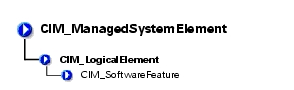
The CIM_SoftwareFeature class shown in Table 3-31 defines a particular function or capability of a product or application system. This class is intended to be meaningful to a consumer, or user of a product, rather than to explain how the product is built or packaged. When a software feature can exist on multiple platforms or operating systems (for example, a client component of a three-tiered client/server application might run on Windows NT), a software feature is a collection of all the software elements for these different platforms. The users of the model must be aware of this situation because typically they will be interested in a subcollection of the software elements required for a particular platform.

Table 3-31. CIM_SoftwareFeature Properties 

Class Name:

CIM_SoftwareFeature

Parent Class:

CIM_LogicalElement

Property

Description

Data Type

IdentifyingNumber

Provides product identification such as a serial number on software.

string

ProductName

Identifies the commonly used product name.

string

Vendor

Identifies the name of the product's supplier. Corresponds to the vendor property in the product object in the DMTF solution exchange standard.

string

Version

Identifies the product version information. Corresponds to the version property in the product object in the DMTF solution exchange standard.

string

Name

Defines the label by which the object is known to the users. This label is a user-defined name that uniquely identifies the element.

string


DELL_SoftwareFeature

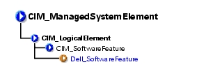
DELL_SoftwareFeature described in Table 3-32 defines the universal resource locator (URL) of the systems management software and the language in which systems management information displays. Defining these properties enables users to manage a system using an Internet browser. You can access Server Administrator using the secure hypertext transfer protocol (https) and a preassigned port number of 1311, or you can specify a port number of your own choosing.

Table 3-32. DELL_SoftwareFeature Properties 

Class Name:

Dell_SoftwareFeature

Parent Class:

CIM_SoftwareFeature

Property

Description

Data Type

OmsaURL

Defines the URL for Server Administrator.

string

Language

Sets the language for systems management information.

string


CIM_SystemResource

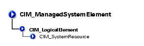
The CIM_SystemResource class listed in Table 3-33 provides access to system resources from an operating system. SystemResources consist of interrupt requests (IRQs) and direct memory access (DMA) capabilities.

Table 3-33. CIM_SystemResource Properties 

Class Name:

CIM_SystemResource

Parent Class:

CIM_LogicalElement


CIM_IRQ

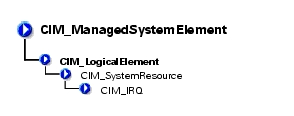
The CIM_IRQ class described in Table 3-34 contains IRQ information. An IRQ is a signal that data is about to be sent to or received by a peripheral device. The signal travels by an IRQ line to the microprocessor. Each peripheral connection must be assigned an IRQ number. For example, the first serial port in your computer (COM1) is assigned to IRQ4 by default.

Table 3-34. CIM_IRQ Properties 

Class Name:

CIM_IRQ

Parent Class:

CIM_SystemResource

Property

Description

Data Type

CSCreationClassName

See Table 1-2, "Common Properties of Classes."

string

CSName

See Table 1-2, "Common Properties of Classes."

string

CreationClassName

See Table 1-2, "Common Properties of Classes."

string

IRQNumber

Identifies the interrupt request number.

uint32

Availability

Indicates the availability of the IRQ. Values for the Availability property are as follows:

  1. Other
  2. Unknown
  3. Available
  4. In use/not available
  5. In use and available

uint16

TriggerLevel

Indicates whether the interrupt is triggered by the hardware signal going high or low. Values for the TriggerLevel property are as follows:

  1. Other
  2. Unknown
  3. Active low
  4. Active high

uint16

TriggerType

Indicates whether edge (value=4) or level triggered (value=3) interrupts occur.

  1. Other
  2. Unknown
  3. Level
  4. Edge

uint16

Shareable

Indicates whether the IRQ can be shared. A value of TRUE indicates that the IRQ can be shared.

Boolean

Hardware

Indicates whether the interrupt is hardware- or software-based. (A value of TRUE indicates that the interrupt is hardware based.) On a personal computer, a hardware IRQ is a physical wire to a programmable interrupt controller (PIC) chip set through which the microprocessor can be notified of time critical events. Some IRQ lines are reserved for standard devices such as the keyboard, diskette drive, and the system clock. A software interrupt is a programmatic mechanism to allow an application to get the attention of the processor.

Boolean


CIM_MemoryMappedIO

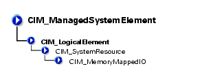
The CIM_MemoryMappedIO class explained in Table 3-35 addresses both memory and port I/O resources for personal computer architecture memory mapped I/O.

Table 3-35. CIM_MemoryMappedIO Properties 

Class Name:

CIM_MemoryMappedIO

Parent Class:

CIM_SystemResource

Property

Description

Data Type

CSCreationClassName

See Table 1-2, "Common Properties of Classes."

string

CSName

See Table 1-2, "Common Properties of Classes."

string

CreationClassName

See Table 1-2, "Common Properties of Classes."

string

StartingAddress

Identifies the starting address of memory mapped I/O.

uint64

EndingAddress

Identifies the ending address of memory mapped I/O.

uint64

MappedResource

Indicates the type of memory mapped I/O. MappedResource defines whether memory or I/O is mapped, and for I/O, whether the mapping is to a memory or a port space. Memory mapped I/O values are as follows:

  1. Other
  2. Mapped memory
  3. I/O mapped to memory space
  4. I/O mapped to port space

uint16


CIM_DMA

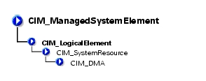
The CIM_DMA class identified in Table 3-36 contains DMA information. A DMA channel allows certain types of data transfer between RAM and a device to bypass the microprocessor.

Table 3-36. CIM_DMA Properties 

Class Name:

CIM_DMA

Parent Class:

CIM_SystemResource

Property

Description

Data Type

CSCreationClassName

See Table 1-2, "Common Properties of Classes."

string

CSName

See Table 1-2, "Common Properties of Classes."

string

CreationClassName

See Table 1-2, "Common Properties of Classes."

string

DMAChannel

Identifies a part of the object's key value, the DMA channel number.

uint32

Availability

Indicates the availability of the DMA. Values for the Availability property are as follows:

  1. Other
  2. Unknown
  3. Available
  4. In use/not available
  5. In use and available/shareable

uint16


CIM_RedundancyGroup

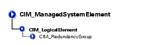
The CIM_RedundancyGroup class shown in Table 3-37 is a set of components that provide more instances of a critical component than are required for the system's operation. The extra components are used in case of critical component failure. For example, multiple power supplies allow a working power supply to take over when another power supply has failed.

Table 3-37. CIM_RedundancyGroup Properties 

Class Name:

CIM_RedundancyGroup

Parent Class:

CIM_LogicalElement

Property

Description

Data Type

CreationClassName

See Table 1-2, "Common Properties of Classes."

string

Name

Serves as the key for the redundancy group's instance in an enterprise environment.

string

RedundancyStatus

Provides information on the state of the redundancy group. Values for the RedundancyStatus property are as follows:

  1. Unknown
  2. Other
  3. Fully redundant. Fully redundant means that all of the configured redundancy is still available.
  4. Degraded redundancy. Degraded redundancy means that some failures have been experienced but some reduced amount of redundancy is still available.
  5. Redundancy lost. Redundancy lost means that a sufficient number of failures have occurred so that no redundancy is available and the next failure experienced will cause overall failure.

uint16


CIM_ExtraCapacityGroup

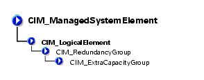
The CIM_ExtraCapacityGroup class explained in Table 3-38 applies to systems that have more capability and components than are required for normal operation, for example, systems that have extra fans or power supplies.

Table 3-38. CIM_ExtraCapacityGroup Properties 

Class Name:

CIM_ExtraCapacityGroup

Parent Class:

CIM_RedundancyGroup

Property

Description

Data Type

MinNumberNeeded

Specifies the smallest number of elements that must be operational in order to have redundancy. For example, in an N+1 redundancy relationship, the MinNumberNeeded property should be set to N.

uint32


DELL_PSRedundancyGroup

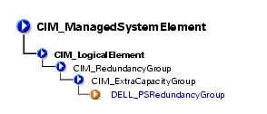
The DELL_PSRedundancyGroup identified in Table 3-39 is a Dell-specific extension of the CIM_PowerSupply class. The DELL_PSRedundancyGroup class defines what constitutes power supply redundancy in a system.

Table 3-39. DELL_PSRedundancyGroup Properties 

Class Name:

DELL_PSRedundancyGroup

Parent Class:

CIM_ExtraCapacityGroup


DELL_FanRedundancyGroup

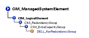
The DELL_FanRedundancyGroup listed in Table 3-40 defines what constitutes fan redundancy in a system.

Table 3-40. DELL_FanRedundancyGroup 

Class Name:

DELL_FanRedundancyGroup

Parent Class:

CIM_ExtraCapacityGroup


Back to Contents Page