Back to Contents Page

CIM_PhysicalElement

Dell OpenManage™ Server Administrator CIM Reference Guide

  CIM_PhysicalElement

  CIM_PhysicalPackage

  CIM_PhysicalFrame

  CIM_Chassis

  DELL_Chassis

  CIM_PhysicalComponent

  CIM_Chip

  CIM_PhysicalMemory

  CIM_PhysicalConnector

  CIM_Slot


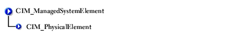
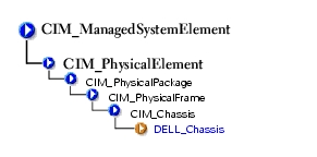
CIM_PhysicalElement is a CIM-defined class. The CIM_PhysicalElement class contains the subclasses shown in Figure 2-1.

Figure 2-1. CIM_PhysicalElement Class Structure


CIM_PhysicalElement

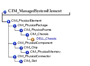
Subclasses of the CIM_PhysicalElement class listed in Table 2-1 define any component of a system that has a distinct physical identity. Physical elements are tangible managed system elements (usually actual hardware items) that have a physical manifestation of some sort. By contrast, processes, files, and logical devices are not classified as physical elements. A managed system element is not necessarily a discrete component. A single card (which is a type of physical element) can host more than one logical device. One card, for example, could implement both a modem and a local area network (LAN) adapter. In this case, the card would be represented by a single physical element associated with multiple logical devices.

Table 2-1. CIM_PhysicalElement Properties 

Class Name:

CIM_PhysicalElement

Parent Class:

CIM_ManagedSystemElement

Property

Description

Data Type

CreationClassName

See Table 1-2, "Common Properties of Classes."


Manufacturer

See Table 1-2, "Common Properties of Classes."


Model

The name by which the physical element is generally known.

string

SerialNumber

A manufacturer-allocated number used to identify the physical element.

string

Tag

Uniquely identifies the physical element and serves as the element's key. The Tag property can contain information such as asset tag or serial number data. The key for physical element is placed very high in the object hierarchy in order to identify the hardware/entity independently, regardless of physical placement in or on cabinets, adapters, and so on. For example, a hot-swappable or removable component can be taken from its containing (scoping) package and temporarily unused. The object still continues to exist and may even be inserted into a different scoping container. Therefore, the key for physical element is an arbitrary string that is defined independently of any placement or location-oriented hierarchy.

string


CIM_PhysicalPackage

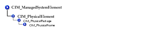
The CIM_PhysicalPackage class listed in Table 2-2 represents physical elements that contain or host other components. Examples are a rack enclosure or an adapter card with multiple functions.

Table 2-2. CIM_PhysicalPackage Properties 

Class Name:

CIM_PhysicalPackage

Parent Class:

CIM_PhysicalElement

Property

Description

Data Type

Removable

A CIM_PhysicalPackage is removable if it is designed to be taken in and out of the physical container in which it is normally found without impairing the function of the overall package.

Boolean

Replaceable

A CIM_PhysicalPackage is replaceable if it is possible to substitute a physically different element for the original element, as in a field replaceable unit (FRU). For example, some computer systems allow the microprocessor to be upgraded to one of a higher clock rating. In this case, the microprocessor is said to be replaceable.

Boolean


CIM_PhysicalFrame

The CIM_PhysicalFrame class described in Table 2-3 contains other frame enclosures such as racks and chassis. Properties like VisibleAlarm or AudibleAlarm, and data related to security breaches are also members of this class.

Table 2-3. CIM_Physical Frame Properties 

Class Name:

CIM_PhysicalFrame

Parent Class:

CIM_PhysicalPackage

Property

Description

Data Type

LockPresent

Indicates whether the frame is protected with a lock.

Boolean

AudibleAlarm

Indicates whether the frame is equipped with an audible alarm.

Boolean

VisibleAlarm

Indicates that the equipment includes a visible alarm.

Boolean

SecurityBreach

An enumerated, integer-valued property indicating that a physical breach of the frame is in progress. Values for the SecurityBreach property are as follows:

  1. Other
  2. Unknown
  3. No breach
  4. Breach attempted
  5. Breach successful

uint16

IsLocked

Indicates that the frame is currently locked.

Boolean


CIM_Chassis

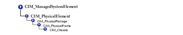
The CIM_Chassis class described in Table 2-4 represents the physical elements that enclose physical elements such as power supplies, fans, and processors.

Table 2-4. CIM_Chassis Parent Properties 

Class Name:

CIM_Chassis

Parent Class:

CIM_PhysicalFrame

Property

Description

Data Type

ChassisTypes

Values for the ChassisTypes property are as follows:

  1. Other
  2. Unknown
  3. Mini-tower
  4. Tower
  5. Space-saving
  6. Main system chassis
  7. Expansion chassis
  8. Subchassis
  9. Space-saving
  10. Main system chassis
  11. Expansion chassis
  12. Subchassis
  13. Bus expansion chassis
  14. Peripheral chassis
  15. Storage chassis
  16. Rack-mount chassis

uint16


DELL_Chassis

The DELL_Chassis class explained in Table 2-5 defines the identifying and status properties of the chassis. DELL_Chassis inherits from CIM-defined classes, but is populated by Dell™ properties.

Table 2-5. DELL_Chassis Properties 

Class Name:

DELL_Chassis

Parent Class:

CIM_Chassis

Property

Description

Data Type

AssetTag

Indicates the container AssetTag string. This asset tag string is writable by the system administrator.

string

SystemClass

Refers to the system type that is installed and running the instrumentation. Values for the SystemClass property are as follows:

  1. Other
  2. Unknown
  3. Workstation
  4. Server
  5. Desktop
  6. Portable
  7. Net PC

uint16

SystemID

Indicates the system identifier code

uint16

LogFormat

Defines whether the event log data is unicode formatted or binary (raw). Values for the event LogFormat property are as follows:

  1. Formatted (event log only)
  2. Unformatted
  3. Events_and_POST_Formatted (both the event log and the power-on self-test (POST) log are unicode formatted)

uint16

FanStatus

Indicates the global status of fan sensors.

string

TempStatus

Indicates the global status of temperature sensors.

string

VoltStatus

Indicates the global status of voltage sensors.

string

AmpStatus

Indicates the global status of current sensors.

string

PsStatus

Indicates the global status of power supplies.

string

MemStatus

Indicates the global status of memory devices.

string

ProcStatus

Indicates the global status of processor devices.

string

FanRedStatus

Indicates the global status of the cooling unit.

string

PsRedStatus

Indicates the global status of the power unit.

string

IsDefaultThrSupported

Indicates whether resetting default thresholds are supported.

Boolean


CIM_PhysicalComponent

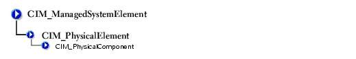
The CIM_PhysicalComponent class listed in Table 2-6 represents any low-level or basic component within a package. A component object either cannot or does not need to be broken down into its constituent parts. For example, an application specific integrated circuit (ASIC) cannot be broken down into smaller discrete parts.

Table 2-6. CIM_PhysicalComponent Properties 

Class Name:

CIM_PhysicalComponent

Parent Class:

CIM_PhysicalElement


CIM_Chip

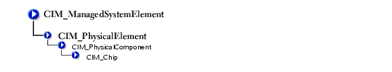
The CIM_Chip class listed in Table 2-7 represents any type of integrated circuit hardware, including ASICs, processors, memory chips, and so on.

Table 2-7. CIM_Chip Properties 

Class Name:

CIM_Chip

Parent Class:

CIM_PhysicalComponent

Property

Description

Data Type

FormFactor

  1. Unknown
  2. Other
  3. SIP
  4. DIP
  5. ZIP
  6. SOJ
  7. Proprietary
  8. SIMM
  9. DIMM
  10. TSOP
  11. PGA
  12. RIMM
  13. SODIMM
  14. SRIMM
  15. SMD
  16. SSMP
  17. QFP
  18. TQFP

uint16

FormFactor

  1. SOIC
  2. LCC
  3. PLCC
  4. BGA
  5. FPBGA
  6. LGA

uint16


CIM_PhysicalMemory

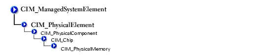
The CIM_PhysicalMemory class described in Table 2-8 is a subclass of CIM_Chip, representing low-level memory devices, such as SIMMS, DIMMs, and so on.

Table 2-8. CIM_PhysicalMemory 

Class Name:

CIM_PhysicalMemory

Parent Class:

CIM_Chip

Property

Description

Data Type

FormFactor

See Table 2-7, "CIM_Chip Properties."

uint16

MemoryType

Indicates the type of physical memory. Values for the MemoryType property are as follows:

  1. Unknown
  2. Other
  3. DRAM
  4. Synchronous DRAM
  5. Cache DRAM
  6. EDO
  7. EDRAM
  8. VRAM
  9. SRAM
  10. RAM
  11. ROM
  12. Flash
  13. EEPROM
  14. FEPROM
  15. EPROM
  16. CDRAM
  17. 3DRAM
  18. SDRAM
  19. SGRAM
  20. RDRAM

uint16

TotalWidth

Indicates the total width, in bits, of the physical memory, including check or error correction bits. If there are no error correction bits, the value in this property should match that specified for the DataWidth property.

uint16

DataWidth

Indicates the data width, in bits, of the physical memory. A data width of 0 and a total width of 8 would indicate that the memory is solely used to provide error correction bits.

uint16

Speed

Indicates the speed of the physical memory, in nanoseconds.

uint32

Capacity

Indicates the total capacity of this physical memory, in bytes.

uint64

BankLabel

A string identifying the physically labeled bank where the memory is located, for example, "Bank 0" or "Bank A."

string

PositionInRow

Specifies the position of the physical memory in a "row." For example, if it takes two 8-bit memory devices to form a 16-bit row, then a value of 2 means that this memory is the second device. 0 is an invalid value for this property.

uint32

InterleavePosition

Indicates the position of this physical memory in an interleave. 0 indicates noninterleaved. 1 indicates the first position, 2 the second position and so on. For example, in a 2:1 interleave, a value of 1 indicates that the memory is in the "even" position.

uint32


CIM_PhysicalConnector

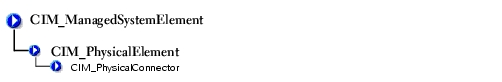
The CIM_PhysicalConnector class explained in Table 2-9 includes physical elements such as plugs, jacks, or buses that connect physical elements. Any object that can be used to connect and transmit signals or power between two or more physical elements is a member of this class. For example, slots and D-shell connectors are types of physical connectors. See Table 2-10 for a list of valid connector type values.

Table 2-9. CIM_Processor Properties 

Class Name:

CIM_PhysicalConnector

Parent Class:

CIM_PhysicalElement

Property

Description

Data Type

ConnectorPinout

A free-form string describing the pin configuration and signal usage of a physical connector.

string

ConnectorType

An array of integers defining the type of physical connector. An array is specified to allow the description of "combinations" of connector information. For example, one array entry could specify RS-232, another DB-25, and a third entry could define the connector as male. See Table 2-10 for the values of the ConnectorType property.

uint16

Table 2-10. Connector Type Values 

  1. Unknown
  1. unused
  1. Micro-DIN
  1. On Board IDE Connector
  1. Other
  1. unused
  1. PS/2
  1. On Board Floppy Connector
  1. Male
  1. IEEE-48
  1. Infrared
  1. 9 Pin Dual Inline
  1. Female
  1. AUI
  1. unused
  1. 25 Pin Dual Inline
  1. Shielded
  1. UTP Category 3
  1. Access. bus
  1. 50 Pin Dual Inline
  1. Unshielded
  1. UTP Category 4
  1. unused
  1. 68 Pin Dual Inline
  1. SCSI (A) High-Density (50 pins)
  1. UTP Category 5
  1. Centronics
  1. On Board Sound Connector
  1. SCSI (A) Low-Density (50 pins)
  1. BNC
  1. Mini-Centronics
  1. Mini-jack
  1. SCSI (P) High-Density (68 pins)
  1. RJ11
  1. Mini-Centronics Type-14
  1. PCI-X
  1. SCSI SCA-I (80 pins)
  1. RJ45
  1. Mini-Centronics Type-20
  1. Sbus IEEE 1396-1993 32-bit
  1. SCSI SCA-II (80 pins)
  1. Fiber MIC
  1. Mini-Centronics Type-26
  1. Sbus IEEE 1396-1993 64-bit
  1. Fibre Channel (DB-9 Copper)
  1. unused
  1. Bus Mouse
  1. unused
  1. Fibre Channel (Fiber Optical)
  1. unused
  1. ADB
  1. GIO
  1. Fibre Channel SCA-II (40 pins)
  1. PCI
  1. AGP
  1. XIO
  1. Fibre Channel SCA-II (20 pins)
  1. ISA
  1. VME Bus
  1. HIO
  1. Fibre Channel BNC
  1. unused
  1. VME64
  1. NGIO
  1. ATA 3-1/2 Inch (40 pins)
  1. VESA
  1. Proprietary
  1. PMC
  1. ATA 2-1/2 Inch (44 pins)
  1. unused
  1. Proprietary Processor Card Slot
  1. MTRJ
  1. ATA-2
  1. unused
  1. Proprietary Memory Card Slot
  1. VF-45
  1. ATA-3
  1. unused
  1. Proprietary I/O Riser Slot
  1. Future I/O
  1. ATA/66
  1. unused
  1. PCI-66 MHz
  1. SC
  1. DB-9
  1. unused
  1. AGP2X
  1. SG
  1. DB-15
  1. unused
  1. AGP4X
  1. Electrical
  1. DB-25
  1. USB
  1. PC-98
  1. Optical
  1. DB-36
  1. IEEE 1394
  1. PC-98-Hireso
  1. Ribbon
  1. RS-232C
  1. HIPPI
  1. PC-H98
  1. GLM
  1. RS-422
  1. HSSDC (6 pins)
  1. PC-98Note
  1. 1x9
  1. RS-423
  1. GBIC
  1. PC-98Full
  1. Mini SG
  1. RS-485
  1. DIN
  1. SSA SCSI
  1. LC
  1. RS-449
  1. Mini-DIN
  1. Circular
  1. HSSC


CIM_Slot

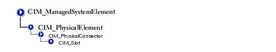
The CIM_Slot class described in Table 2-11 represents connectors into which packages are inserted. For example, a physical package that is a hard drive can be inserted into an small computer system interface-single connector attachment (SCSI-SCA) slot. As another example, a card can be inserted into a 16-, 32-, or 64-bit expansion slot on a host board.

Table 2-11. CIM_Slot Properties 

Class Name:

class CIM_Slot

Parent Class:

CIM_PhysicalConnector

Property

Description

Data Type

ConnectorType

See Table 2-10

uint16

SupportsHotPlug

Indicates whether the slot supports hot-plug adapter cards.

Boolean

MaxDataWidth

Indicates the maximum bus width in bits of adapter cards that can be inserted into this slot. Values for the MaxDataWidth property are as follows:

  1. Unknown
  2. Other
  3. Bits
  4. Bits
  5. Bits
  6. Bits
  7. Bits

uint16


Back to Contents Page