Fig. 1 the focals of conical mesh and circular mesh
Recent research [1] about discrete surfaces for architectural design presents some elegant mesh study methods by using the concept of parallel mesh. By using mesh parallelism, we can get some interesting features of circular meshes, conical meshes [2] and edge offset meshes [3], as well as the relations between them. Circular meshes and conical meshes, which process vertex offset meshes and face offset meshes, respectively, are very useful especially in multi-layer architecture design. In some cases, we want to convert a mesh between a conical mesh and a circular mesh, such that both of them represent the same underlying surface. In [1], the authors provide a method to construct a circular mesh from conical mesh, or construct a conical mesh from a circular mesh. They also provide a method, by which we can construct a conical mesh from a circular mesh via the concept of polar duals. The purpose of this project is to implement and analyze the construction of a circular mesh from a conical mesh via the concept of polar duals. Other than translating the faces of the polar duals of circular mesh, which is mentioned in [1], I provide a new method to construct. This project was written in Matlab.
In this section, I briefly introduce some concepts and lemmas close related to my project.
Circular mesh is a quad mesh whose quads are not only planar, but also have a circumcircle. Moreover, circular mesh m possesses an offset mesh m' such that corresponding vertices of m and m' lie at constant distance (vertex offset). Any circular mesh is parallel to a mesh m0 whose vertices lie in a unit sphere.
Conical mesh is a PQ mesh, and all of its vertices of valence four are conical, which means all the four oriented face planes meeting at this vertex are tangent to a common oriented cone of revolution. Moreover, conical mesh l possesses an offset mesh l' such that corresponding oriented face planes of l and l' lie at constant signed distance (face offset). Any conical mesh is parallel to a mesh l0 whose face planes are tangent to a unit sphere.
Focal is the intersection point of neighboring axes (for conical meshes) or normal (for circular meshes), see Fig. 1 from [1].
Fig.
1 the focals of conical mesh and circular mesh
Polar duals: if PQ mesh m and l are called polar duals of each other, if the vertices of m are contained in the unit sphere S2, and the face Fij of the mesh l are the polar duals of the vertices mij. A circular mesh which approximates a unit sphere, has a polar dual which is a conical mesh. Conversely, a conical mesh circumscribed to a unit sphere has a polar dual which is a circular mesh.
There are five steps to construct a circular mesh from a conical
mesh, which are
1, Get a conical mesh as the input mesh for our
algorithm.
2, Get tangent points of the faces of l0 to
a unit sphere S2.
3, Get axis directions of every cone
of the conical mesh.
4, Use the concept of mesh parallelism to
construct a circular mesh.
First of all, by using the method provided by [2], we can get a conical mesh (denoted as l) as input of our algorithm. See Fig. 2
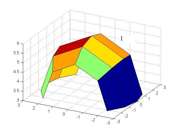
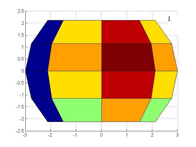
Fig.
2 a 5*5 conical mesh generated by perturbation method
According to the normals to the faces of the conical mesh l, we can get the tangent points of the faces of l0 to a unit sphere S2. Again, l0 is a conical mesh parallel to l and all of its faces are tangent to a unit sphere. See Fig. 3 left. Then we connect these tangent points orderly. See Fig. 3 right. What we get is a circular mesh (denoted as m0). Furthermore, it is the polar duals of the l0, although we still do not get the l0 explicitly.
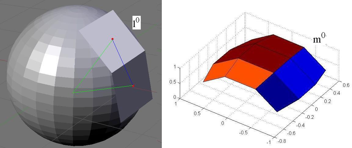
Fig. 3 left: the parallel conical mesh's tangent points to a unit sphere. Right: its polar duals(circular mesh)
After getting these tangent point, we can get part of the vertices of l0, which is the all the cone axes of l0. See Fig. 4. Line pass through a vertex and any one tangent point around the vertex is a tangent line to the unit sphere. Actually, what we need are the axis directions of every cone of the conical mesh l, which is the input mesh.
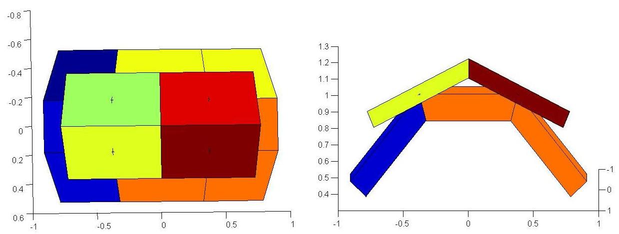
Fig. 4 vertices of the conical mesh l0
Unlike the method presented in [1], I do not do any translation. I use the concept of mesh parallelism to construct a circular mesh (m) from the conical mesh (l). As we all know, any circular mesh is parallel to a mesh (here it is m0), whose vertices lie in a unit sphere. Then we need to find a set of points on the faces of l, such that edges produced by connecting them are parallel to m0's corresponding edges respectively.
By studying the principle of conical mesh, I found I can get those circular mesh's vertices using the informartion of focals of the conical mesh l. From a focal, I make 4 lines which are perpendicular to faces around it. Now we can get 2 faces which are parallel to the corresponding 2 faces of m0 respectively (actually it is a translating face planes of m0). See Fig. 5, modified from [2].
Fig. 5 the focal and the circular mesh constructed using the focal
However, there is a weakness of my method. Because not all axes of cones intersect in one focal. As a result, the two perpendicular line of one face plane are not coincident. See the red line and the blue line in Fig. 6. Meanwhile, the focals from the row strips are not coincident with those from column strips. See Fig. 1 for detail.
Fig. 6 weakness of my method: the different focals do not give the same perpendicular point to a face plane
I solve this problem by dividing the mesh to several parts, making sure the focal of every part is unique and independent to others. Take Fig. 7 for example, those 9 red points, I can generate them by using the method present above. They are unique. After that, I use the mesh parallelism to get three white points. Then using the same method, we can get those 4 yellow points.
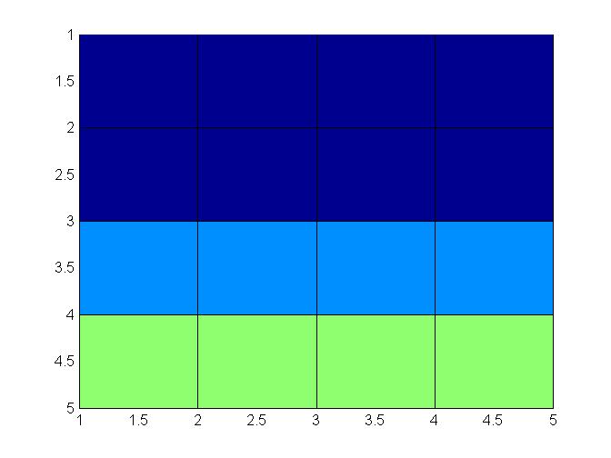
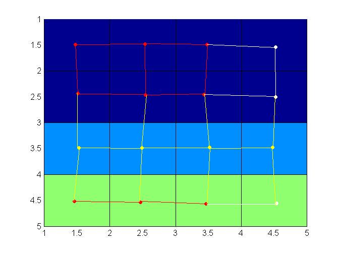
Fig. 7 focals are different between row strips and column strip, it cause the same problem as Fig. 6. My method to solve the problem
Finally, I get a circular mesh from a conical mesh, such that both of them represent the same underlying surface.
Here I show 2 results of my method. See Fig. 8 and 9.
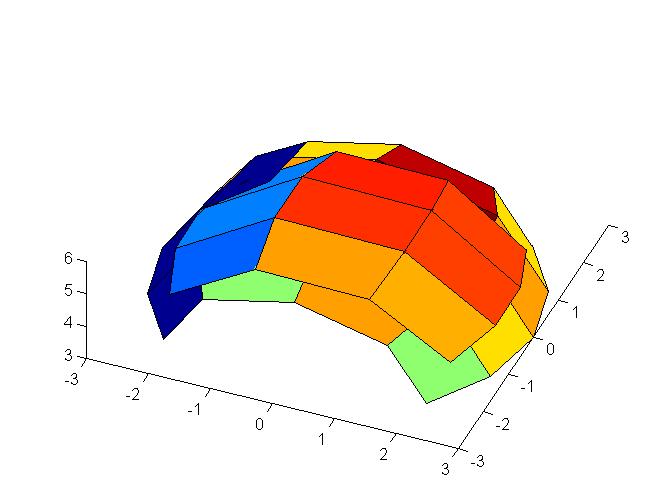
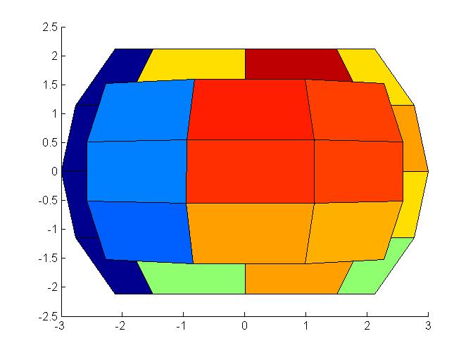
Fig. 8 Conical mesh 5*5 and its circular mesh 4*4
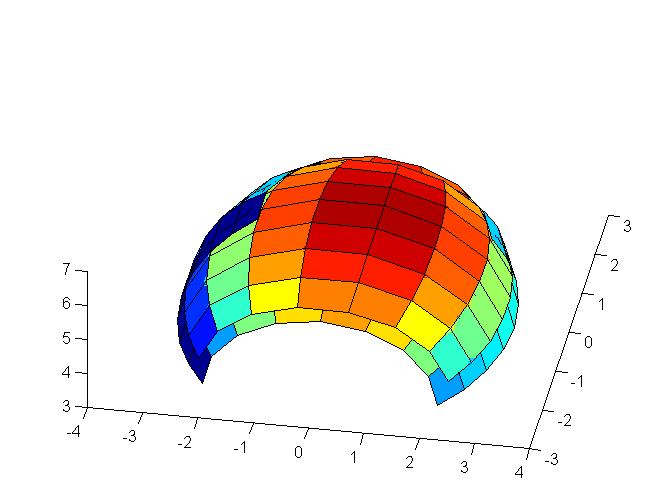
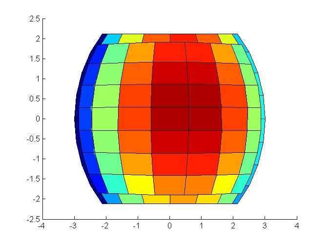
Fig. 9 Conical mesh 9*9 and its circular mesh 8*8
Difference: Mesh translation v.s. mesh parallelism. In this project, I use a different approach to construct a circular mesh from a conical mesh. In [1], authors provide a construction method of a conical mesh from a circular mesh. First, constructing m0, then find l0 by polar duality, and translate the face planes of l0 to l, which pass through the vertices of m. Although, they did not mention how to construct a circular mesh from a conical mesh in similar way, in my opinion, the procedure would be similar: first, constructing l0, then find m0 by polar duality, and translate the face planes of m0, until vertices touch the faces of the conical mesh l.
However, it is not easy to get the translation for every face plane, such that all of the faces will connect to each other at the vertices. In this project, I present a new method, which is mainly based on the concept of mesh parallelism. In addition, I include the focals of the conical mesh, in order to take advantage of conical meshes' good properties.
Strengths: My method makes full use of the vectors direction information of the conical mesh. We know those normal of the faces. What I need is to calculate the focals. It's easy to implement. At contrast, translating faces and making sure all of them intersect in the vertices, needs to do face scaling. Therefore, it is not easy to implement. Moreover, because this method divides the mesh quite evenly, the accumulating error, which would be big problem in pure mesh parallelism method, can be limited in my method.
Weakness: This method does not fit for the whole mesh. It still needs to calculate some points using mesh parallelism.
What I have learned: I know the properties of conical mesh and circular, and their relations. I begin to understand how discrete surface for architectural design works.
Future work: According to [4], all edge offset meshes have a parallel mesh whose edges are all tangent to a unit sphere. When I was working on this project, I also tried to construct edge offset mesh. See Fig. 10. However, although every edge of this "mesh" is parallel to a tangent line to a unit sphere, its faces are not all planar. In the future, we may try to modify this method, in order to construct edge offset mesh from a conical mesh or a circular mesh.
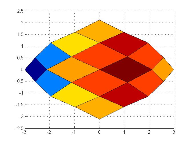
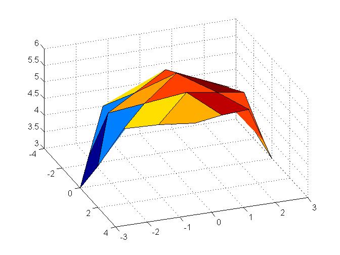
Fig. 10 "Edge offset" mesh
[1] Helmut Pottmann and Johannes Wallner. The Focal Geometry of Circular and Conical Meshes. Advances in Computational Mathematics,vol.29,no.3,pp.249-268,Oct. 2008.
[2] Yang Liu, Helmut Pottmann, Johannes Wallner, Yong-Liang Yang and Wenping Wang. Geometric Modeling with Conical Meshes and Developable Surfaces. ACM Transaction on Graphics, vol. 25, no. 3, pp. 681-689, 2006.
[3] Helmut Pottmann, Yang Liu, Johannes Wallner, Alexander Bobenko and Wenping Wang. Geometry of Multi-layer freeform Structures for Architecture. ACM Transactions on Graphics,vol.26,no.3,pp.65-1-11,July 2007.
[4] Helmut Pottmann and Sigrid Brell-Cokcan. Discrete surfaces for architecutral design. Curves and Surfaces: Avignon 2006. P.Chenin et al., Eds. Nashboro Press.