The Sound of Math
(notes in progress by Prabhakar Ragde, see inspirations and sources at the end)
Our goal is to discuss some connections between mathematics and sound, specifically music created on electronic synthesizers. To set the stage, let’s briefly discuss what sound is, and how we can abstract sufficiently to be able to apply mathematics and computation. This material is aimed at students in their first year of university study. The mathematical requirements are exposure to trigonometric and exponential functions, complex numbers, and \(\Sigma\)-notation for sums. Some experience with definite integrals and linear algebra would help, but the concepts are briefly sketched, and not relied upon heavily.
1 The nature of sound
Imagine a player of a stringed instrument, a guitar or violin. The instrument has several strings stretched taut over a fingerboard. The player plucks one of the strings with their right hand, first gently, to produce a soft note, then more vigourously, to produce a louder note. Then they use their left hand to bring the string into contact with the fingerboard at one point, effectively reducing the length of the string. When they pluck again, the note produced is higher in pitch.
What is happening here? Briefly, sound is our perception of waves of air pressure. An ocean wave is a variation of water height that appears to be travelling horizontally, though in fact individual water molecules are mostly moving up and down, and a bit sideways. Similarly, a sound wave is a variation of air pressure that appears to be travelling outward from the source of the sound.
The plucked string is vibrating rapidly and creating the sound wave by physical interaction with the air. A shorter string will vibrate more rapidly, though the tension in the string also plays a role. The changes in air pressure make our eardrums vibrate. Those vibrations create waves of pressure in the fluid of our inner ears. Tiny hairs in our inner ears move in response to those pressures, and electrochemical impulses travel via nerves to our brain. Finally, our brain interprets the information.
That’s a lot of complicated physics, biology, and chemistry, but we don’t need to fully understand it all. The most important facts are that we perceive the extremes of pressure (like the height of the ocean wave, or the distance the vibrating string is travelling) as the volume or amplitude of sound, and the rate of change of pressure (how fast the string is vibrating) as the pitch of a sound.
It is possible to discuss some relationships between mathematics and music without involving electricity. Ancient cultures around the world worked out some of these. While we still can make or listen to music created on physical acoustic instruments, more often we listen to recorded music played back through speakers or earbuds, and electricity is used in playback, recording, and possibly in the instruments themselves. So a little more background will be helpful.
2 Analog and digital
Speakers and earbuds use electromagnetism to create sound. A magnet moved near a coil of wire will create a flow of electrical current. Conversely, a flow of current in a coil of wire can move a magnet. A speaker has a two-dimensional membrane with a magnet at the centre that is moved by electrical flow.
If we imagine the flow of electrons in a wire as similar to the flow of water in a pipe (this analogy is very limited, but suffices for our purposes), the electrical quantity corresponding to pressure is voltage. Speakers are constructed so that higher voltage moves the magnet (and thus the speaker membrane) further, resulting in louder sound when the membrane is moving back and forth rapidly. The rate of change of air pressure (which we perceive as pitch) is directly related to the rate of change of voltage.
We have arrived at the mathematical quantity that we can work with: voltage as a function of time. The unit of voltage is the volt (named after Alessandro Volta, who first constructed a battery in 1799) and abbreviated with a capital V, so we can speak of 5V or five volts. An electronic musical instrument creates a rapidly-varying voltage, which when used to drive a speaker, produces music. But there is one further complication, whose effects will sometimes be noticeable in what we do.
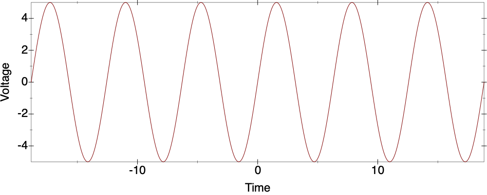
If we were to graph the voltage in the wire going to a speaker, it would be a smooth, continuous curve. We can think of real numbers being used on both the x-axis (time) and y-axis (voltage).
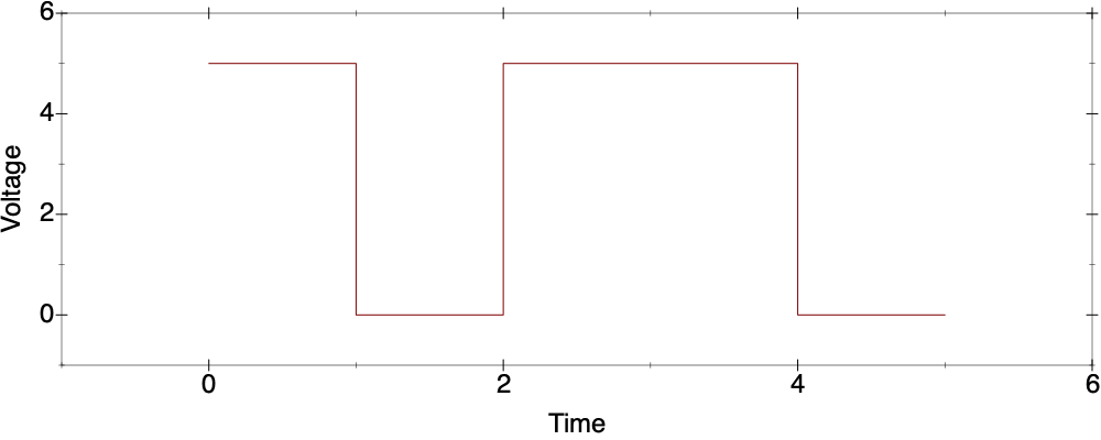
A central operating principle of computers is that voltage is treated in a discrete fashion, with only two possibilities: low (close to 0V) and high (close to 5V). This digital interpretation (as opposed to the more continuous analog interpretation) makes it easier to deal with the accumulation of errors caused by the physical properties of circuits. Our graph becomes a series of horizontal line segments.
In some situations (for example, a digital recording, such as a WAV file), the time domain is considered as discrete also, so the graph becomes a series of disconnected dots, evenly spaced on the time dimension.
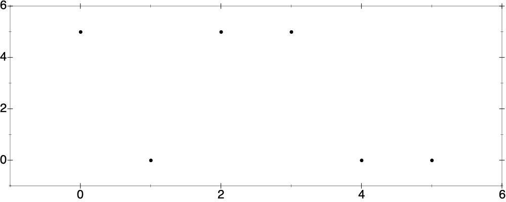
We could further abstract this using the bits 0 and 1, and represent this by the sequence 101100. A WAV file uses more than two values on the voltage dimension, but still a fixed number of evenly-spaced values.
There are many analog electronic instruments. One can buy one for as little as a hundred dollars. But you probably own the computer on which you are reading this, and we will be using free software that simulates an analog electronic instrument or synthesizer. This choice is mostly for convenience, but it is one made by many professional musicians and sound engineers. There are many digital electronic instruments, and digital technologies are heavily used in recording and distribution. It’s not uncommon to see a full live concert performed primarily on a laptop.
3 Our instrument: VCVRack2
Analog synthesizers can be a single box with complete functionality, but another approach is to divide things up into smaller units or modules with specific functionality, which are mounted in a rack and interconnected with cables. There are several standards, but the most popular one is Eurorack.
VCVRack2 is software that simulates Eurorack. There is a free version (for MacOS, Linux, and Windows) which comes with a limited set of modules, which will be good enough for us to get started. Free registration on their site will give you access to a library of modules, many free (including some provided by manufacturers of physical Eurorack modules) and some that cost money. You can also pay for an upgrade to the software for more professional capabilities. Registration and upgrading are optional if you decide to continue using the software after this.
(If you’re reading this on your smartphone and not a laptop or desktop, there is an adaptation available for iOS, but it’s not free.)
Download VCVRack2 and install it. When you open it up, it will load a default template with a number of modules and cables (wires) between them. The look is skeumorphic (imitating a physical rack), down to the rows of screwholes, the screws on the modules, and even the power headers in the bottom of the case from which power cables would run to individual modules. Rather than explain the default template, we will start with an even simpler configuration. Download the file Start0.vcv and open it in VCVRack2.
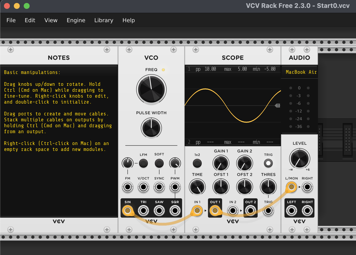
You will see four modules. To the far left is the Notes module, which just contains some text about basic use (how to turn knobs, how to manipulate cables). There are also tooltips and a link to the manual (on the VCVRack website) in the Help menu.
The next module to the right is labelled VCO. This stands for Voltage-Controlled Oscillator. It will produce a voltage that oscillates (moves up and down) with a range of -5V to 5V. The big knob controls the frequency, or rate of change, which we perceive as pitch. If you hover over it, a popup shows its value, 220Hz. Hz is the abbreviation for hertz, the unit of frequency (1/seconds), named after Heinrich Hertz, who demonstrated electromagnetic waves in 1886. The SIN output of VCO will produce a sine wave. Since the period of the mathematical sine function is \(2\pi\), the expression for the voltage with frequency \(f\) measured in Hz at time \(t\) is \(5\sin (2\pi ft)\).
If you have played a musical instrument, you may know that 440Hz is standard concert tuning, the A just above middle C, and 220Hz is the frequency of the A just below middle C. If you haven’t, don’t worry about this for now; it will be explained a bit more later.
There is a cable going from the SIN output of VCO to the IN 1 input of the SCOPE module to its right. This is simulating the transmission of the voltage from the VCO to the SCOPE module, a simulated oscilloscope, which displays waveforms. The IN 1 input goes directly to the OUT 1 output of SCOPE, and there is a cable from that to the L/MON input of the AUDIO module to the right. L/MON is short for "left or mono". We are generating only one sound voltage, so the same sound will be heard in both ears of headphones or earbuds, and from each of a pair of stereo speakers.
But you probably aren’t hearing any sound. There are two reasons for this. One is that you need to tell the AUDIO module how you are listening to your computer, by clicking on the black panel at the top of the module and selecting the appropriate output destination. The other reason is that the level knob is turned all the way down. Turn it up to taste.
You are hearing a sine wave! It is a pure, clean sound, perhaps a little dull. Move the frequency knob and listen to the pitch change. For a more interesting sound, drag the cable from the SIN output to the TRI (triangle) output. Same pitch, same volume setting, but it sounds more complex, and a little louder. The differences between sounds that are not due to volume or pitch are lumped under the vague term timbre.
The triangle wave doesn’t look like a triangle on SCOPE. The sides are curved, like a sail or shark’s fin.

This is a simulation of what an analog circuit would actually produce. Often sine waves are produced by using a triangle-core VCO and having the triangle shaped by other circuitry to approximate sines.
For more drastic changes in timbre, drag the cable from the TRI output to the SAW (sawtooth) or SQR (square) output. These are definitely richer sounds. Sawtooth is an idealized version of the sounds produced by bowed string instruments such as violin, and square sounds more like wind instruments such as clarinet. You will notice more oddities on SCOPE where the lines are supposed to be vertical.

This is due to decisions made to produce good sound in this digital simulation, rather than mathematically exact waveforms. There is further explanation on the manual webpage for VCO, though you may understand it better after what follows.
4 Vibrato and FM
We’ve been speaking of voltage as a representation of a sound. But it can also be used to modulate or change that sound. This is apparent in the abbreviation VCO, where the first two letters stand for Voltage-Controlled. Another common abbreviation is CV, for "control voltage".
Download the file Vibrato.vcv and open it in VCVRack2.
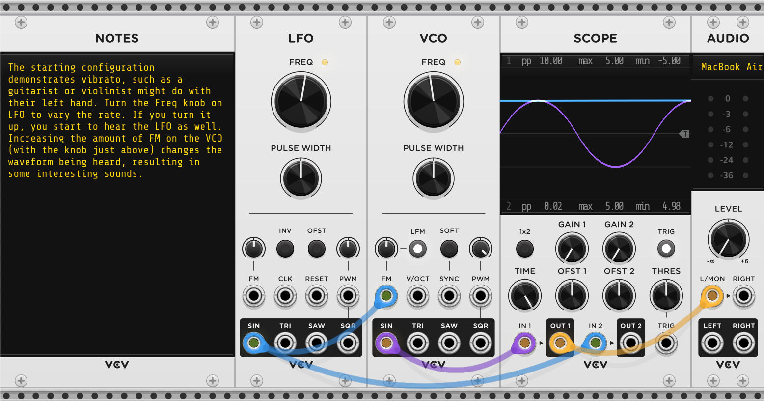
Compared to the configuration in the previous section, there is one new module, LFO. The name is an abbreviation for Low-Frequency Oscillator. It basically does the same thing as VCO, but the range of the frequency knob is different, as are some of the controls.
If you hover over the frequency knob of LFO, you will see that it is oscillating at 3Hz, or three times a second. You can see this relatively slow oscillation on SCOPE, which is one of the places that the SIN output of LFO is going. The other place is the FM input on VCO. FM stands for "frequency modulation". The voltage coming in here is added to the frequency selected by the VCO frequency knob, though it is first reduced by the knob just above the FM input. This attenuverter (attenuator with the possibility of inversion) has its zero position at 12:00 (the top of the knob), and if you hover over it, you’ll see that it’s only letting 1% of the LFO output in.
You should be disturbed at the statement that the voltage is added to the frequency. They have different units! This is resolved by the V/oct standard, which is a convention for how to convert between frequency and voltage. We’ll talk more about this below. A physical knob on an electronic musical instrument simply affects a control voltage in the circuitry just below it, and that is what in turn affects the functioning of the instrument.
The effect of connecting LFO to VCO in this fashion is roughly the same as if we could grasp the frequency knob of VCO and slightly wiggle it back and forth about three times a second. The musical effect is known as vibrato. You see it in action when a violinist rocks their left hand slightly to slightly change the length of the string they are holding down, or when an electric guitarist wiggles the "whammy bar" hanging down just below where they strum with their right hand. (Vibrato on a violin is not symmetric about the original pitch the way ours is; it drops below but does not go above.)
The chosen frequency for the LFO is in the range of what a human musician could do with their hands, though the amount is a bit too much (so it is really obvious to you, but that means the effect is not as musical). Turning up the frequency knob quickly takes it out of the range of human possibility. If you turn it up even higher, something interesting happens: you start to hear the LFO, even though it is not connected directly to the audio voltage path.
Take the frequency of the LFO to near 110Hz by hand (you don’t have to get it exact, and it’s more interesting if you don’t). Then slowly turn up the FM attenuverter on VCO. You should hear and see the waveform from VCO get more complex. This is known as FM synthesis. It is capable of a wide variety of sounds, some of which resemble ones that can be produced physically, and some that have no such counterpart. The idea of FM was used in radio broadcasting starting in the 1930s, but its application in music is due to John Chowning (1973). Yamaha licensed his patent, and the resulting Yamaha DX7 synthesizer played a significant role in the electronic pop sound of the 1980s. The FM technique works best with sines, but it can be used with other waveforms.
What is the difference between audio voltage and control voltage? The only difference is that audio voltage should be audible. If we connect the LFO sine output with frequency 110Hz directly to the AUDIO input, it won’t sound any different from the VCO sine at 110Hz (at its original tremolo setting, it wouldn’t be audible). If we want to work with audio-rate modulation, we could just replace LFO with a second VCO. LFO also has an FM input, so whether or not we do this replacement, we could have the two oscillators cross-modulate each other. We could add even more LFOs and VCOs.
Now you perhaps start to see the appeal of a modular approach. You can plug any output into any input and see what happens. Perhaps nothing at all will happen, perhaps nothing interesting, but perhaps something fascinating and/or musically useful.
Apart from the appearance of sine waves, we haven’t seen much serious mathematics so far. That will change in the next section. The mathematics of what you heard in this section is somewhat complicated, but we’ll say a little about it below.
5 Adding two sines
Download the file Sum2Sines and open it in VCVRack2.

Here we have two VCO modules, whose outputs are mixed in the VCA MIX module. VCA stands for Voltage-Controlled Amplifier, but just as we first turned the frequency knob of VCO by hand, in this section we are going to push the voltage sliders of VCA MIX by hand.
Initially the original VCO is set to 220Hz, just as before, and the added VCO is set to 440Hz, twice as fast. The cable going from the SQR output of the slower VCO to the TRIG input of SCOPE stabilizes the waveform display (take away the cable to see what the effect is, if you’re curious).
Turn up the volume in AUDIO and listen to the two together. Take the slider for channel 1 of VCA MIX down to the bottom to hear just the VCO playing 220Hz, and then bring it back up to -4dB and take the slider for channel 2 all the way down to hear the other VCO.
dB stands for decibel, the bel being a unit of volume named for Alexander Graham Bell, who invented the telephone in the 1870s. It uses a logarithmic scale, so reducing amplitude by half is a decrease of about 6dB, no matter what the original amplitude was.
The relationship between the frequencies 220Hz and 440Hz sounds good to us. For this reason, the interval between a frequency and double that frequency is given a special name: it is an octave (because there are eight notes before the octave is reached in Western musical scales). In Western musical notation, notes an octave apart are denoted by the same letter. 440Hz is A4, 220Hz is A3.
Other whole number ratios also sound good. If we multiply 440Hz by 3/2, we get 660Hz. Try listening to those together. This interval is called a perfect fifth, and it would correspond to the note E5. 660Hz (E5) and 880Hz (A6) also sound good together. This is a perfect fourth with ratio 4/3. A scale tuned this way uses just intonation.
And yet, on an electronic keyboard, E5 would have the frequency 659.26Hz instead of 660Hz. Why? Consider this thought experiment. Going up a fifth from A4 to E5 and down a fourth gets us to B4. So the ratio between A4 and B4 should be (3/2)(3/4) or 9/8. On a piano keyboard, there is a black key between these two white keys, but some white keys are adjacent (B and C, and again F and G). So repeating this going up and down a total of six times should get us to the octave A5. But the resulting ratio is not 2. It is 9/8 raised to the sixth power, or roughly 2.027.
The practical effect of this is that with just intonation, one cannot simply transpose a piece of music (have it start on a different note but retain the same melody) because the whole-number ratios will not be preserved in the new setting, unless the transposition is an octave. The ratios of the intervals in the transposed piece could be slightly off, and this effect can be audible.
The solution adopted for electric pianos (and to a large extent for acoustic pianos, with a small adjustment due to the physical characteristics of the instrument) is to use equal temperament. The ratio between two adjacent keys on a keyboard (a semitone, of which there are twelve between a note and the one an octave higher) is the 12th root of 2. So a perfect fourth (five semitones) on a keyboard has a ratio which is the 12th root of 2 raised to the fifth power, about 1.33484 instead of 4/3. But that ratio remains the same no matter where the lower note is.
Why are there twelve semitones in an octave? Because if we climb by a perfect fifth twelve times, we reach a note with a frequency that is \((3/2)^{12}\) higher, or about 129.75, which is very close to \(2^7\) or seven octaves, and the notes we hit along the way constitute the semitones (within different octaves, of course). This is the "circle of fifths", and the gap is known as the "Pythagorean comma". Equal temperament can be viewed as a method to effectively distribute the gap and thus minimize its effect. The seven notes of a diatonic scale (the white keys on a keyboard) can be reached with six perfect fifths.
Now that we understand the relationship between frequency and notes in a Western musical scale, we can talk about the V/oct standard. This is simple: a change of 1V means a change of one octave, and a change of 1/12V means a change of one semitone in equal temperament. Of course, we don’t have to apply a multiple of 1/12V to a V/oct input, so we can use other tunings as well.
Players of fretless string instruments (violin, cello) will tend to use just intonation when playing with each other. When playing with a piano, they will adapt a little towards equal temperament. Piano tuning is complicated and is done infrequently as needed, but string instrument players will tune every time they play (sometimes between sections of a longer piece). It’s hard to listen to a reference note and then stop it and try to match it. But when the reference note and the instrument being tuned are played together, an interesting phenomenon called "beating" happens, and this can be used to facilitate tuning.
You can hear it with this VCVRack2 patch. Set one VCO to 440Hz and the other to 444Hz. You should hear a slightly unpleasant sound that is pulsing in volume. You can see the volume change on the AUDIO module’s display. Control-drag (command-drag on a Mac) the higher one and pull down slightly to lower it just a bit. The rate of the pulsing should decrease. Without looking at the displayed frequency, keep lowering it in this fine-grained way until the pulsing disappears, at which point both oscillators should be at 440Hz. This is what players do to tune their string instruments. How close did you get?
We can explain this phenomenon with mathematics. Here is a trigonometric identity involving the sum of two sine waves of different frequency.
\[\sin \alpha t + \sin \beta t = 2\cos\left({\alpha - \beta \over 2}t\right)\sin\left({\alpha + \beta \over 2}t\right)\]
(Challenge: prove this from scratch, starting with geometric proofs of identities for \(\sin(x+y)\) and \(\cos(x+y)\).)
In our application, \(\alpha\) and \(\beta\) are the frequencies, and they are quite close together. So \(\alpha - \beta \over 2\) is small, and \(\alpha + \beta \over 2\) is very close to (in between) \(\alpha\) and \(\beta\). (Here \(\alpha\) and \(\beta\) are not the frequencies expressed in Hz; because the period of the sine function is \(2\pi\), one has to divide by this number.)
We can interpret the \(\sin\) term on the right-hand side of the identity as supplying the frequency of the sound we are listening to, and the \(\cos\) term as determining the volume, which is slowly changing with time (pulsing or beating). As we adjust \(\beta\) to make it closer to \(\alpha\), the beat frequency decreases, and we use that to approach the tuning we want.
Slightly detuned oscillators are used in electronic music. For example, slightly detuned saws have a thicker, richer sound that changes with time, so they are good for "pads" (long sustained notes). The slight drift of analog oscillators means that there might not be a single beat frequency; rather, the changes are more random and organic-sounding. Gamelan is a traditional Indonesian percussive ensemble, and the Balinese version uses instruments that are deliberately detuned for the beat effect.
6 Tremolo and AM
Download the file Tremolo and open it in VCVRack2.
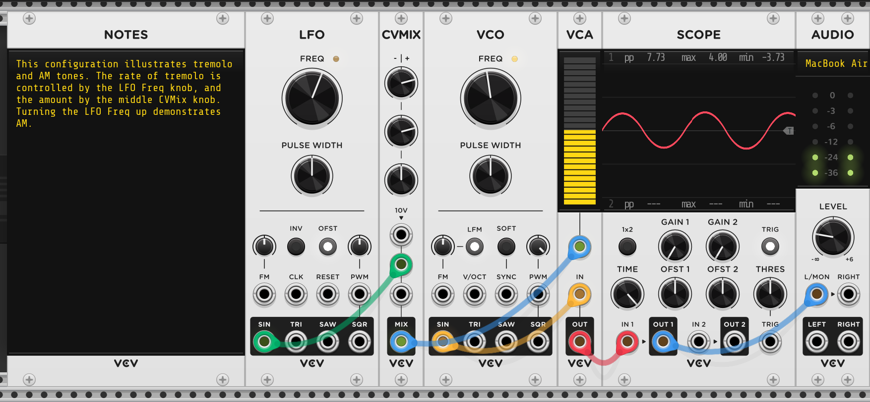
This configuration explores amplitude modulation (AM). There is only one VCO. In place of VCA MIX from the previous patch, there are two simpler modules, VCA (remember, this means Voltage-Controlled Amplifier, and here we are actually using the voltage control) and CVMIX, which is like the MIX part of VCA MIX but intended for control voltage.
The output of CVMIX is going into the top input on VCA, which provides voltage control of amplitude or volume. The top input of CVMIX is attenuated (actually attenuverted) by the top knob, but nothing is plugged into that input. The little annotation above it informs us that 10V is provided in this case, so the input provides a constant offset set by the knob, and in this case we are using it for base volume. But that volume is affected by the other inputs to CVMIX, and the middle input is connected to the output of the LFO. The corresponding attenuverter lets us reduce the effect of the LFO, and it has been set to provide only slight variation.
The combined effect is called tremolo. The word is sometimes used for the whammy bar on electric guitars, but that is incorrect; as mentioned above, the whammy bar varies pitch to produce vibrato. On an acoustic guitar, one only has control over the initial volume by how hard a string is plucked or strummed. With an electric guitar, a tremolo effect pedal can be used on the electrical output of the guitar. With bowed string instruments, where the bow has to be continuously moving to produce the sound, the word "tremolo" is used for a rapid back-and-forth movement using the tip of the bow, which has a similar effect.
As with vibrato, it is interesting to turn up the LFO past the point that a human player might achieve, and into the range where the LFO would be audible on its own. Try this. The effect is more complex, but not as interesting as FM. This is known as amplitude modulation, or AM. Once again, it was a technique used in early radio. It is easy to achieve in modular synthesis, but is not as widely used, because it isn’t as interesting musically. Why not?
A little mathematical analysis combined with what we’ve learned above sheds light on this. The key equation is:
\[(A + B\sin\beta t)\sin\alpha t = A\sin\alpha t + {B\over 2} (\cos(\alpha-\beta)t - \cos(\alpha+\beta)t)\]
Challenge: prove this from scratch. If you did the previous challenge, you’ve already done some of the work needed, because you know how to express \(\sin(x+y)\) and \(\cos(x+y)\) in terms of products like \((\sin x)(\cos y)\). The rest is just algebraic manipulation.
We can interpret the first term on the right-hand side as the original audio without AM. The second term adds two sounds with the same amplitude, one with frequency \(\alpha - \beta\), and one with frequency \(\alpha+\beta\). You know that a cosine wave is just a sine wave starting in a different place, and the same is true for a negated sine or cosine, so they’re all going to sound like sine waves.
Will this sound nice? It will if \(\alpha\) and \(\beta\) are in whole-number ratio relationships, because then their sum and difference will be also. But it’s only two added sounds, and varying the amount of modulation (\(B\) in the equation above) only varies the volume of the added sounds in the same way, so the potential for complexity is limited.
Why does FM sound so much better? The sound is more complex, but so is the math. John Chowning’s 1973 paper explains it for the closely related concept of phase modulation (PM). (We’ll discuss below why the PM math also applies to FM.)
If the modulating sine wave is applied to phase, we get an expression like \(A\sin(\alpha t + B \sin \beta t)\). We can use the \(\sin (x+y)\) identities from above to deal with this, but we are left with a trig function applied to another trig function, which is not an elementary topic. You are not going to be able to deal with this from scratch. Here’s the relevant identity.
\[A\sin(\alpha t + B \sin \beta t) = A \sum_{n=-\infty}^{\infty} J_n(B) \sin((\alpha + n\beta) t)\]
Here the J’s are Bessel functions, which are defined using definite integrals. Without knowing more, we can view the \(J_n(B)\) terms as constants affecting the amplitude of the added sounds. The important thing is the frequencies. They are of the form \(\alpha + n\beta\), for integer \(n\). So instead of the two added frequencies from AM, we have an infinite number of sidebands from PM (and also FM). Again, if \(\alpha\) and \(\beta\) are in a harmonious relationship, the sidebands will tend to be as well. That is why we had you choose frequencies in a whole-number ratio for your experiment with FM above. Varying the amount \(B\) of modulation will vary the mix of the sidebands in a complex fashion depending on the properties of the Bessel functions. Inharmonious FM also has its uses; it can easily produce metallic or glassy sounds.
7 Envelopes and kick drum
If one plucks a taut string, the sound does not sustain indefinitely like the output of VCO. It rises quickly in amplitude and then falls away more slowly as the string loses energy. It does not repeat like the output of LFO. This suggests a need for a module that provides CV that has this one-shot shape or envelope.
ADSR is such a module. The acronym stands for "attack, decay, sustain, release". The envelope is triggered by a gate which is digital-like, in that it has a low (off) setting and a high (on) setting. Think of these as being generated by pressing a key on an electric piano or synthesizer. Attack sets the time for the envelope to rise to its peak, and decay the time for it to fall to its sustain level. The CV holds at this level for as long as the gate is high; when the gate goes low, release indicates the time it takes for the CV to reach zero.
These four parameters are chosen for maximum flexibility, and they don’t all need to be used. A percussion instrument like a drum will tend to have a very short attack and a slightly longer decay, but no sustain or release. A plucked guitar string will have a short attack and a much longer decay, if it is not stopped or re-fretted. A piano, which is at heart a percussion instrument, has a sustain pedal, but this does not sustain the sound at the same level; it merely keeps the dampers from stopping the note. So a piano has short attack and moderate delay, or short attack and longer decay. An organ has very short attack, no decay, sustain at full volume, and very short release. But in the electronic setting, one can craft interesting sounds with no physical analogues that use all four parameters. There are also envelope modules with even more parameters, because envelopes can be applied to other inputs besides volume on a VCA. The next patch illustrates this.
Download the file KickDrum.vcv and load it into VCVRack2.
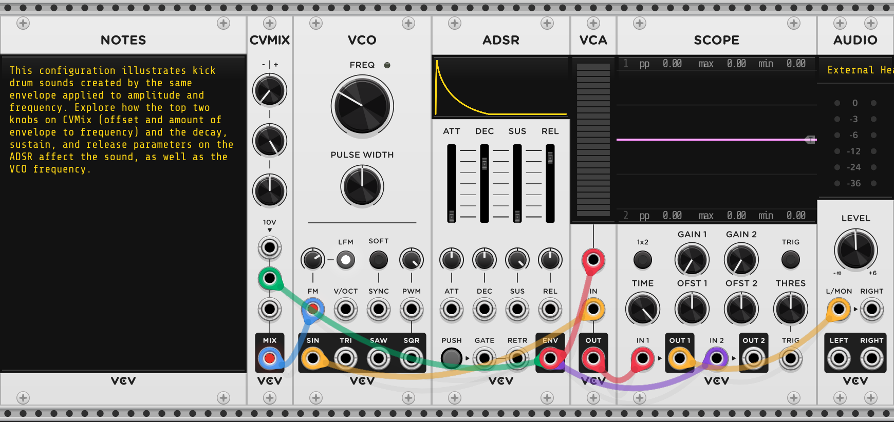
The display of the envelope on ADSR is not as accurate as SCOPE. For one thing, the sustain part is not shown. The scale is also not consistent. It’s more of an illustration. You will notice that the lines are not straight. Decay and release are negative exponential functions, of the form \(Ae^{-kt}\). Attack is an inverted version of this.
This configuration doesn’t have a way of generating gate signals to trigger the envelope, but the ADSR module has a manual push button we can use (which will sustain if you click-and-hold). The cables are set up so that the envelope is not only used for the CV of VCA as described above, but also for the FM input of VCO. So the frequency of the oscillator also rises and falls following the contour of the envelope. Here is another place where a sine wave is useful, as we don’t want higher harmonics in a kick drum. CVMIX is not doing much in the initial configuration; it is there for your experimentation.
The resulting sound is not quite like an acoustic kick drum, but is more reminiscent of the electronic drums used in techno, EDM, and other electronic genres. There are a lot of parameters for you to experiment with. Some settings will give "pew-pew" or "laser" sounds. Other settings may resemble other types of percussion. If you get tired of pushing the trigger button manually, add LFO and use its square output as a gate. You can vary the time on vs off with the pulse width knob. For a less repetitive sequence, use the SEQ 3 module, which provides eight steps and three channels of CV plus a possible trigger for each step. You can build your own groovebox!
We are very close to having the ability to create a minimal classic synthesizer in VCVRack. The one thing we lack is a way to provide precise voltages representing notes we want to play to the V/oct input of VCO. This is provided by the MIDI-CV module, described in the Core Modules section of the VCVRack2 manual. If you download the file MinimalSynth.vcv, it is already configured for you.

MIDI is a digital standard for transmission of musical information, many decades old. The MIDI-CV module has been configured to let you use your computer keyboard to play notes. Certain keys will play certain notes (look at the documentation to find out which, or just experiment). There is a V/oct output with a cable already going to the V/oct input of VCO, and a gate output going to the gate input of ADSR. The gate stays high as long as you hold down a key. The synth is monophonic (one voice); you cannot play multiple notes at the same time. Polyphony (many simultaneous voices) is possible in VCVRack2, but not with a computer keyboard.
You are of course free to experiment and to add more modules. The square and saw outputs may be too harsh-sounding without using filters, as described in a later section.
8 Summing many sines
We’ve seen that summing two sines of different frequencies can lead to an interesting waveform. AM gave us the sum of three sines, and FM the sum of an infinite number (though only a finite number are audible to us). What might be possible if we sum multiple sines? The answer may surprise you.
If we repeat a waveform, we get a periodic function, that is, \(f(t)=f(p+t)\) for all \(t\) (where \(p\) is the period of the function). Under certain conditions required to rule out pathological cases and ensure convergence of the resulting infinite series, \(f\) can be expressed as the sum of sines. And not just any sines! The slowest one has the same period as \(f\), so frequency \(\alpha=2\pi/p\). The rest of the sines have frequencies that are integer multiples of \(\alpha\).
More precisely, there exist coefficients \(A_n\) and \(\phi_n\) such that for all \(t\),
\[f(t) = A_0 + \sum_{n=1}^{\infty}A_n\sin(n\alpha t + \phi_n).\]
This is the Fourier series for \(f\). The frequencies \(n\alpha\) are called harmonics or partials, and the first one \(\alpha\) is called the fundamental. That tend to be the pitch we perceive. We heard above that adding a strong second harmonic can be heard as two notes, but in general, the rest of the harmonics tend to affect the timbre of the sound. The coefficients \(\phi_n\) are called phase shifts (they affect the relative position of zero crossings). These phase adjustments cannot be heard in isolation, but they have a cumulative effect. The idea of the theorem is due to Joseph Fourier (1807), and the concept is known as Fourier analysis, though many other mathematicians contributed to developing the theory.
Mathematically, this is interesting, but musically speaking, it gives us a way to discuss timbres. The sine sounds plain because it has no added harmonics; the sawtooth sounds rich because it has a lot. But how much, and which ones?
For the sawtooth, the phase shifts are all zero (as is the coefficient \(A_0\), which is the average of \(f\) over one period) and the coefficients \(A_i\) are proportional to \(1/i\). If we drop all the coefficients of even index to zero, keeping only the fundamental and the other odd harmonics, we get a square wave! These two waves have discontinuities, so that alone is not a violation of the conditions of the theorem. But \(f\) may not be perfectly reproduced at a discontinuity, so the equality sign above requires some qualification.
Creating interesting waveforms by adding sines is known as additive synthesis. It would be expensive to do with physical analog circuits, but is easier with digital simulations. We can do a bit of this in VCVRack2.
Download the files AdditiveSaw.vcv and AdditiveSquare.vcv.
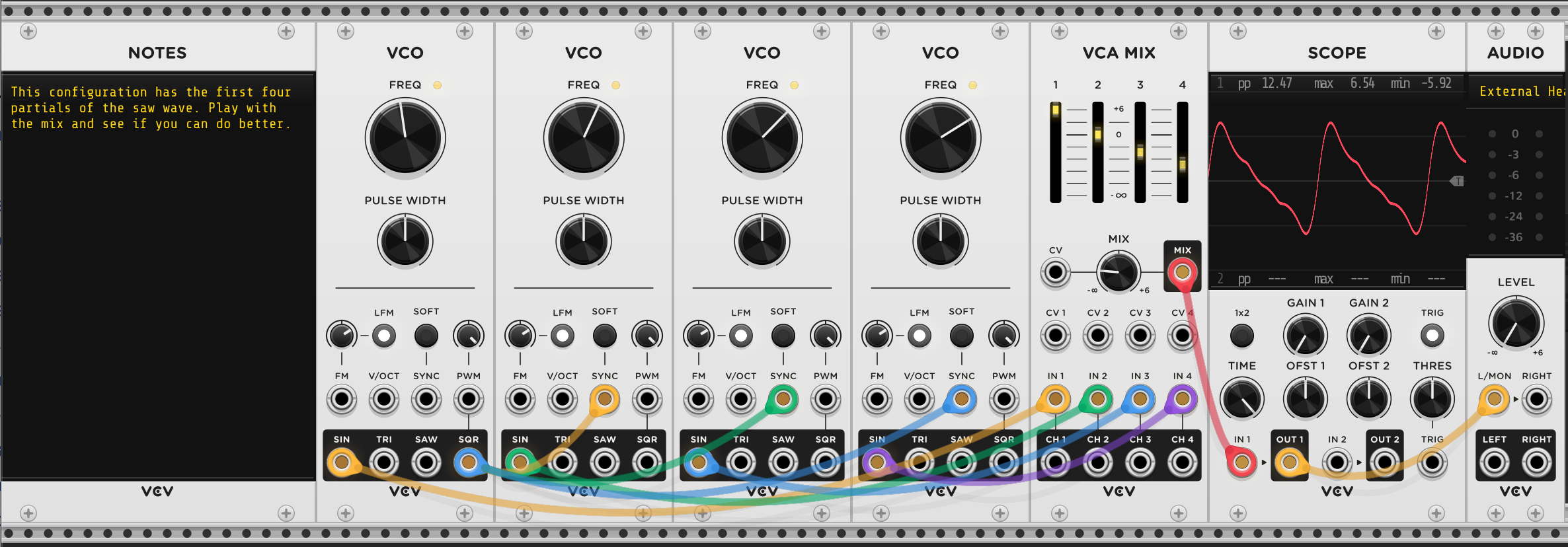
AdditiveSaw has four VCOs (hey! they’re free!) tuned to 220Hz, 440Hz, 660Hz, and 880Hz. The coefficients can be adjusted by the VCA MIX sliders. AdditiveSquare has the same arrangement, but the VCOs are tuned to 220Hz, 660Hz, 1100Hz, and 1440Hz. VCO does not have a way to do phase shifts, but they are not needed for these two waveforms. See if you can improve the shape of these approximations (or, more importantly, the sound).
The sawtooth and square waveforms can be produced by simpler analog circuits without mixing sines in this fashion. These waveforms can then be used for subtractive synthesis by removing harmonics with the use of filters. We will discuss filters below.
Some of these concepts inform the design of physical Eurorack modules. Here is a picture of one, Generate 3, made by Joranalogue.

This is a triangle-core VCO, and in the lower right section of the faceplate, one can see the CORE output. But there are also outputs labelled FUND (fundamental), ODD, and EVEN. The FUND output provides a sine wave at twice the frequency of CORE (and derived from it). The other two outputs provide a mix of harmonics of the fundamental. The EVEN output is a saw wave at twice the frequency of the fundamental. It thus provides all even harmonics of the fundamental. The ODD output provides the odd harmonics above the fundamental. Thus mixing the FUND and ODD outputs can create a square wave. There are knobs and CV inputs for each of these, and a mix of FUND, EVEN, and ODD is available at the FULL output.
You can also see some CV inputs and knobs available on VCO, for FM and synchronization. There is also a PHASE knob and CV input. As previously mentioned, a phase shift is not really audible, but if audio-rate modulation is used with the CV input, the resulting effect is similar to FM. Just plugging the CORE output into the PHASE input and turning the knob results in some interesting timbral changes. In fact, the Yamaha DX7 mentioned above uses phase modulation. Generate 3 is a waveshaping laboratory.
Derivation of the formula for computing the coefficients of a Fourier series for a given function is best appreciated after a course in complex analysis, but we can sketch some of the ideas. Euler’s formula relates the complex exponential function to trigonometric functions: \(e^{i\theta}=\cos\theta + i\sin\theta\) where \(i=\sqrt{-1}\). We usually start talking about complex numbers using Cartesian coordinates, as \(x + iy\), but Euler’s formula motivates the use of polar coordinates to express a complex number as \(r(\cos\theta + i\sin\theta)\), where \(r\) is called the absolute value, magnitude, or modulus, and \(\theta\) is called the factor or argument. Here \(r\) is the distance of the point \((x,y)\) from the origin, and \(\theta\) is the angle that the corresponding line makes with the x-axis.
The exponential function is easier to manipulate algebraically. To that end, we rewrite the Fourier series for \(f\):
\[f(t) = A_0 + \sum_{n=1}^{\infty}A_n\sin(n\alpha t + \phi_n).\]
to use the exponential function, resulting in this form:
\[f(t) = \sum_{n=-\infty}^{\infty}c_n e^{in\alpha t}.\]
Here the coefficients \(c_n\) are complex-valued. From these, using Euler’s formula, our earlier real-valued coefficients \(A_n\) and \(\phi_n\) can be easily extracted.
The formula for computing the coefficients uses a definite integral, the continuous version of a sum, which can be thought of as computing the area under a curve (at least for real-valued functions, though we need to use complex-valued functions). The area under the curve of the function \(g(x)\) in the x-interval \([a,b]\) is written \(\int_{a}^b f(x) dx\). As an example, \(\int_{0}^{2\pi}\sin x ~dx = 0\), since the area below the x-axis is a negative contribution.
With some algebraic manipulation of the formula for \(f\) above, and an integration over one period of the function, that is, over the interval \([0,P]\) where \(P = 2\pi/\alpha\), one can derive the formula:
\[c_n = {1 \over P} \int_{0}^{P} f(t)e^{-in\alpha t} dt.\]
The derivation is not very long, but it takes more work to establish the conditions under which the infinite sums involved are guaranteed to converge. These conditions are satisfied by any analog signal that might be produced by electronic equipment, but there remain gaps between theory and practice that we will address.
The theory can be extended to aperiodic functions, by considering what happens as \(P\) approaches infinity (so \(\alpha\) would approach zero). With some more manipulation, we get the following form.
\[\hat f(\phi) = \int_{-\infty}^{\infty}f(t)e^{-i 2\pi\phi t} dt\]
This is the Fourier transform, taking a function \(f\) in the time domain into a function \(\hat f\) in the frequency domain. For a specific frequency \(\phi\), \(\hat f(\phi)\) is a complex number whose magnitude gives the amplitude of the component of the sound (assuming \(f\) represents a sound) at that frequency, and the argument gives its phase shift. An aperiodic function has no fundamental frequency, so the word "harmonic" can refer to any frequency.
The Fourier transform is invertible (again, under certain reasonable conditions) with the following analogue of the Fourier series (the infinite sum becomes an integral):
\[f(t) = \int_{-\infty}^{\infty}\hat f(\phi)e^{i 2\pi\phi t} d\phi\]
Fourier transforms of various sorts have important applications in many fields. Fourier’s original motivation was in thermodynamics. The theory can also be extended to functions that are discrete in the time domain. For some functions \(f\), a closed form for \(\hat f\) can be derived using techniques from complex analysis. Other functions will have no closed form solutions, and the integrals must be manipulated, or computational approximations used.
Another way to look at these concepts is by generalizing ideas from elementary linear algebra. Any vector in \(\mathbb{R}^n\) can be written as a linear combination of the \(n\) standard basis vectors. In fact, our usual notation for these vectors just lists the coefficients of the linear combination, for example, \(\begin{bmatrix} 3 \\ 4 \end{bmatrix} = 3 \begin{bmatrix} 1 \\ 0 \end{bmatrix} + 4 \begin{bmatrix} 0 \\ 1 \end{bmatrix}\). The standard basis vectors form an orthonormal basis, where the dot product of any two different vectors is zero, and the dot product of a basis vector with itself (that is, its length or magnitude) is 1.
Similarly, the functions \( \{e^{in\alpha t}\}\) for integer \(n\) form an orthonormal basis for the inner product space of periodic functions (that meet certain conditions) with fundamental \(\alpha\). In this setting, the dot product, which with \(\mathbb{R}^n\) is a sum of products of corresponding coordinates from two vectors, becomes an inner product, an integral of the product of two functions. Once we define the idea of projecting one vector onto another using the dot product, the coefficients of an arbitrary vector in \(\mathbb{R}^n\) can be expressed in terms of projections onto the standard basis vectors. That is what the quoted formula for the coefficients of a Fourier series is doing in the new context. The theory of vector spaces includes these two seemingly quite different situations as particular examples.
With the concepts introduced in this section, we can now consider the relationship between FM and PM. Recall that we considered the expression \(A\sin(\alpha t + B \sin \beta t)\) to explain the many sidebands that occur with FM and PM. This is modulating the phase with a sine wave of frequency \(\beta\). To use this expression to explain frequency modulation, where some \(f\) is modulating the frequency \(\alpha\) of the carrier, the relationship we need (as defined in the earliest mathematical treatments of FM) is that frequency is the derivative of phase, and phase is the integral of frequency.
Thus by integrating our frequency modulation function, we get the corresponding phase modulation. But the derivative of a sine term is a cosine term, which is just a sine with a phase shift, and the same is true for integrals. So the mathematical treatment of FM using sines is very similar to that of PM using sines. Of course, the implementations of these can vary considerably and act differently in practice, since physical analog oscillators have triangle or sawtooth cores, and we are not restricted to using sine waves for either carrier or modulator.
9 Analog and digital revisited
Now that we understand more about what VCVRack2 is simulating, it’s time to explore some of the consequences of this digital simulation, which also involve interesting mathematics. Analog circuits do an imperfect job of implementing mathematical concepts (the square and sawtooth waveforms they produce do not have discontinuities, but very steep slopes). Or, to shift perspectives, mathematics does an imperfect job of modelling reality (though many mathematicians, scientists, and engineers put a lot of work into narrowing those gaps). Digital processing presents its own (and often related) set of challenges.
As mentioned briefly at the beginning, to move from our idealized mathematical conception of sound as a voltage-time graph, we have to discretize in both the time domain and the voltage domain. A WAV file contains samples taken at 44100Hz, each sample a 16-bit quantity, which we can think of as an integer between 0 and 65535 inclusive, or these scaled to be equally spaced between -5V and 5V in our standard voltage-time view.
Graphically, these are dots approximating some continuous curve which is either the original source of audio, or the eventual audio to be played. If these are samples of an analog signal, they will have come from an analog-to-digital converter, often abbreviated A/D converter or ADC. If we want to play them, they need to go through a digital-to-analog converter (D/A converter or DAC). This is also the case for digital signals generated in real time with a program like VCVRack2. There are versions of these converters that are cheaper, and ones that are more expensive, because there are choices to be made, and tradeoffs.
As a thought experiment, let’s consider a bad example of a DAC, just drawing straight lines between the points on the graph. The resulting sharp corners are going to need very high harmonics to approximate well. But human hearing is in the range 20Hz to 20000Hz (with individual variation, and changes with age). Speakers might not even span this full range. There’s no point in producing sounds that people won’t hear. If some of those harmonics are audible, chances are they aren’t or weren’t intended to be in the original source material, so they may not sound good with it.
We are left with the question: at what rate and with what resolution should we sample analog audio, and how can we get as close as possible to recreating it from the samples?
A remarkable theoretical answer is given by the Nyquist-Shannon theorem (also shown earlier by Whittaker, but often just referred to by Nyquist’s name). This states that if a function has no harmonics at frequency \(\alpha\) or higher, then it can be exactly reconstructed by samples at a rate \(2\alpha\) or higher. The proof of this theorem, not surprisingly, uses the Fourier transform, and is not difficult.
There are two major practical problems in applying this theorem. The larger one is that the theorem talks about samples over time (so the time domain is discretized) but the samples are real numbers (the voltage domain is not discretized, whereas it would be in computation). The smaller but still significant problem is that DACs and ADCs make compromises for practical reasons which can introduce further errors.
The theorem suggests that the sampling rate of WAV files (44100Hz or 44.1kHz) is adequate for sounds meant to be heard by humans. But the practical considerations mentioned above cast some doubt on that. A further complication is that WAV files are large, so often the information is compressed in various ways (MP3s and their successors, streaming algorithms). Can one hear the result of these compromises? People have been arguing about sound fidelity for as long as electromechanical reproduction has been possible, and they aren’t going to stop any time soon. VCVRack2’s default sample rate is 48kHz, but this is configurable in the Engine menu if you want more of a margin of confidence.
We can see the effect of some of these issues in the glitches in the saw and square waveforms displayed on SCOPE. If the Nyquist bound is not respected, then reconstruction can introduce aliasing, which is the creation of harmonics that do not exist in the original signal. These harmonics might not be multiples of the fundamental and so can sound harsh or odd. The word "alias" can mean a different name for the same thing. It is used here because the proof of the reconstruction theorem shows that violating the bound can introduce copies of the original waveform that are shifted and scaled in time (which we perceive as shifted in frequency).
An anti-aliasing algorithm in VCVRack2 makes sure this doesn’t happen by removing high harmonics. But if only low partials of a discontinuous signal are summed, the Gibbs phenomenon occurs, which is, colloquially speaking, glitchiness at the discontinuity. The region where this happens narrows as more partials are added, but it never quite disappears.
These decisions are taken to improve sonic character, which is what we should care about, rather than what the waveform looks like.
It should not surprise you that a lot of work has been done in improving computational efficiency of the Fourier transforms from the time domain to the frequency domain and back again, especially in the discrete sampling context. Extensions of the theory are needed for real-time applications. But these are topics for advanced study.
10 Filters
Removal of harmonics can be done with filters, which are important tools in subtractive synthesis. The physical characteristics of the analog circuits that do filtering have some interesting musical consequences, to the point where these characteristics are simulated in digital applications such as VCVRack. Filters have many uses outside of music (for example, to remove noise resulting from interference with a signal).
The effect of a filter could be difficult to describe in the time domain, but it is easier in the frequency domain. A lowpass filter removes harmonics above a given cutoff frequency. An ideal lowpass filter would do nothing to harmonics below the cutoff frequency, and totally remove those above it. Such a mathematically ideal filter is used in the proof of the Nyquist-Shannon theorem and the consequent reconstruction algorithm.
But practical analog filter circuits tend to have a removal effect which starts at the cutoff frequency and gets stronger above it. A typical filter circuit designed for music might have a rolloff of 6dB/oct. For example, if the cutoff frequency is 220Hz, then the effect at the filter output on the harmonic at 440Hz (one octave higher) would be 6dB lower (half the amplitude). That is a gentle effect, and a steeper rolloff can be achieved by putting two or more of these circuits in series, to achieve rolloffs of 12dB/oct, 18dB/oct, or 24dB/oct.
Download Filter.vcv and load it into VCVRack2.
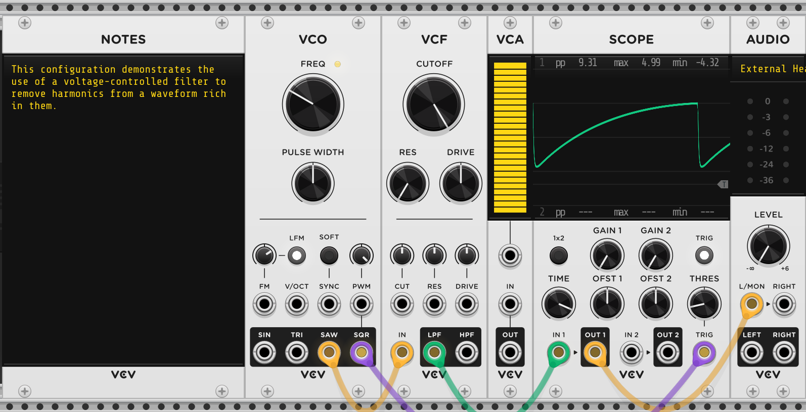
This configuration has the VCF (voltage-controlled filter) module filtering the saw output of VCO. Turn the volume on AUDIO up to taste, and turn the cutoff knob on VCF down to hear the effect of a sweep. SCOPE can only show you the effect in the time domain, but you can see something is happening, at least. If you register on the VCVRack2 website, you can install a free spectrum analyzer module, which can show you the effect in the frequency domain. The frequency-time graph it will show will have vertical spikes at the harmonics, and those will be reduced by VCF’s lowpass output at a rate of 24dB/oct above the cutoff frequency.
The CV input for cutoff allows it to be modulated by an envelope, an LFO, or another VCO (for filter FM). The DRIVE knob (and CV input) simulates what happens with an analog filter circuit when the input amplitude is high or "overdriven". It is a type of distortion that can add character to a sound. The HPF output implements a highpass filter, which removes all frequencies below the cutoff frequency, with a rolloff extending below. Putting a LPF and an HPF in series will create a bandpass filter, and putting them in parallel will create a notch or bandstop filter.
The RES knob and CV input simulate another characteristic of analog circuits, which is that they resonate. This manifests as a possible small peak in the frequency domain at the cutoff frequency, the amount of which can be controlled. The resulting small amplification effect there can be musically pleasing. Turn the RES knob to 12:00 and sweep the cutoff knob to hear this effect.
When resonance is turned up high, some filters (including the simulation in VCF) will self-oscillate, making sound at the cutoff frequency without the need for input. This oscillation is truly sinusoidal in nature, unlike the oscillators described above which derive sines from triangle or sawtooth waveforms using waveshaping. If the cutoff CV input tracks V/oct (which takes work, so it’s not always implemented, but it is in VCF), the filter can be played musically. Another possibility is to put the resonance just below self-oscillation, and send a gate or trigger into the filter input. This "pings" or excites the filter into emitting a burst of sound, which can sound like a percussion instrument. Some analog filters are prized mainly for these last two qualities, rather than for their core filtering ability.
Unfortunately, the resonance in the VCF simulation is not particularly interesting. There are filters with more character in the free ones available with VCVRack registration, or you can look for "acid techno" on your favourite streaming media, a genre where the squelchy resonance of a filter is prominent in lead lines. Ironically, this genre started when Roland, a large instrument manufacturer, released the TB-303 in 1981. It was oversold as a replacement for a bass guitar, which it was not, and it was discontinued as many devices showed up cheaply in second-hand stores. Impoverished musicians bought them and turned their defects into virtues.
Though VCF is not suitable for acid, the patch Banjo.vcv uses it to create a sound reminiscent of a banjo, though it certainly wouldn’t be confused for one.
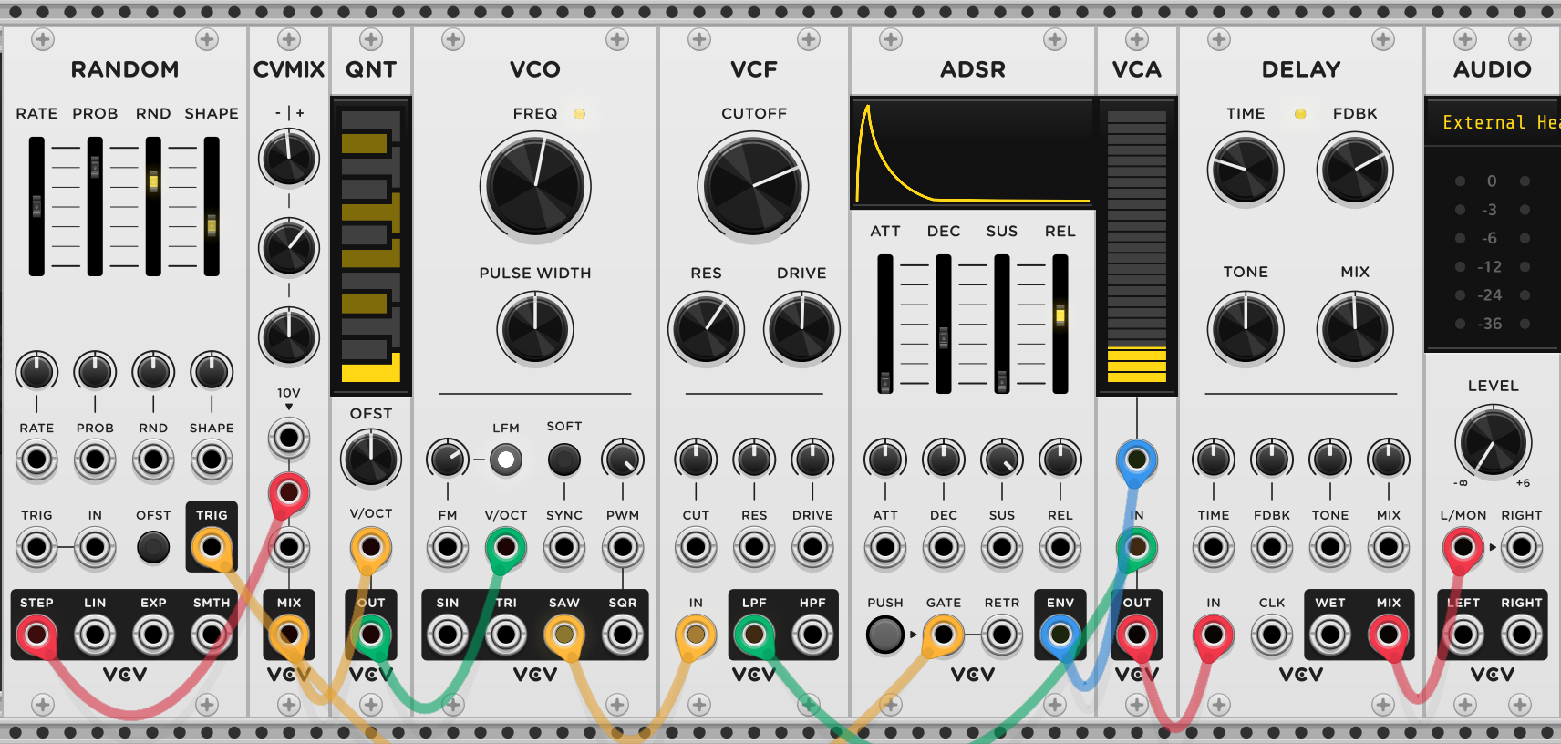
The musical line is automatically generated by the RANDOM module, whose output is attenuated by CVMIX and quantized to a minor pentatonic scale by QNT. There is no reverb effect in the basic VCVRack2 modules, but DELAY provides an echo effect, and with short echo times, this adds some ambience. There is a lot here for you to experiment with, and many concepts whose mathematics and physics you may wish to explore further.
If VCVRack sparks an interest in modular synthesis using physical Eurorack, I have a flânerie on the subject, with a chapter where I explain the design of a VCVRack built using only free modules that simulates a reasonable starter physical rack, using as much as possible modules that have actual physical counterparts or are close replicas.
11 Sources
I took inspiration for this flânerie from a sound-based "Math Days" activity in the Faculty of Mathematics at the University of Waterloo, in turn adapted from "Tron Days" held as part of a discipline-specific introductory course in the Mechatronics program. That activity primarily used Audacity to generate waveforms and listen to them.
Here are the contributors for that earlier work:
Engineering coop students: Maggie Lambe, Vincent Gervais-Leduc, Peter Lee, Iris Quan, Sohee Yoon.
Faculty and staff from Engineering: Sanjeev Bedi, Mohammed Nassar, Chris Rennick.
Faculty from Mathematics: Andrew Beltaos, Eddie Dupont, Carrie Knoll, Kirsten Morris, Francis Poulin.
From the "Math Days" activity, I took the idea of the beat frequency phenomenon, the kick drum design, and the use of VCVRack, which was brought in at the very end, with one 17-module rack implementing a "retro synth". I felt that VCVRack would be better used from the very beginning, and in smaller configurations.
For some of the mathematical details, I consulted the online textbook Signals and Systems (Baraniuk et al.), released under the LibreTexts umbrella with a CC BY 4.0 license (I rewrote said details in my own words).
In turn, this work is licensed under a Creative Commons Attribution-NonCommercial-ShareAlike 4.0 International License.