- direct command choosing from different menus
- direct mouse manipulation
From the users point of view these two ways are equivalent in the final result.
By those two ways you can:
- Insert in your document any graphical element that specified in the Pic language:
- box , arrow , ellipse , circle, line, scale, spline , arc , text
- Specify directions , that influence the rest of the picture:
- up , down , left , right
- Define element parameters:
- size ( width , height , radius )
- line style ( solid , dotted , dashed , invisible )
- places ( at , with ... at )
- adjustments (above , below , right , left )
- arc directions ( clockwise)
- Use default parameters
- scale , boxwid , boxht , linewid , lineht , circlerad , arcrad , ellipsewid, ellipseht,
- movewid , moveht
- If you want to insert in your document the same picture more than once or if you want draw different geometric objects depend on some condition there are defined the operator:
- for ... to ... by ...
What really will be discussed :
Operations that you can perform using the product functionality which is specified by WYSIWYG approach ( by the way we cover almost everything that defined in the Pic so we assume it will be enough)
- Those functions for working with files
- New
- Open
- Save
- Save as
- Print preview
- InsertFile(add some file at given position)
- AppendFile(add some file at the end of the editing)
- Quit
- Those functions for document editing
- Clear
- Select All
- Move ( Manipulation with group of elements )
- Cut
- Copy
- Paste
- Delete
- Undo
- Redo
- Properties
- Those functions for geometric elements drawing:
- Box
- Circle
- Line
- Spline
- Arrow
- Ellipse
- Arc
- Text
- Same
- Move ( pic element)
- Those built in function:
- for...to...by...
- It is possible to define a label that simplifies the working with object locations.
- Also user can insert in object some text ( associated text ) or write something he want to add to edited document (standalone text)
- Those allow to view a wanted document:
- View source (open separate window with a source text of the current picture)
- Text editor (open text editor with a source of the current picture)
- Specific Options:
- Scale
- Set defaults
- Grid settings
- Label view on/off ( if user may see labels)
- And Help availiable in next forms:
- About the program
- Help Index
- Tutorial
- You working with base cursor if no special mode mentioned below has been activated
- Cursor for At,To position operations is '+'.By it user locate desired point on the screen for further operations.
- Cursor for getting help on graphic interface componenets: '?'
- text window always available.
- some functions on right button of mouse
- choosing current object or group of objects by clicking on it
- changing size of object by dragging it
- changing position of object using direct mouse manipulation
- deleting number of objects using direct mouse manipulation
- loop copying element or group of elements using direct mouse manipulation
- for current object always available all functions in right button
- indicating attributes like at , from , to by clicking on appropriate point
- change all objects parameters by changing it attributes directly
- button for changing line style and font settings
- button for fill bounded elements (circles,boxes and ellipses)
- attaching label to object by clicking on mouse
- indication insertion point by clicking on mouse
- changing line style and palette for particular element by direct mouse manipulation
In all chapters we try to keep next constrains to facilitate your efforts understanding the manual
- Text related to the diagrams signed by < > tags ,for example box with text <box>
- All definitions we make typed using Italic font style.
- All new terms signed using Bold font style.
- 1.From the beginning
- All pic language diagrams are based on basic pic elements. There are: box, ellipse, circle, line, arrow, arc, text and move. All elements have their own attributes like position, line style or associated text.
- Pic compiler uses those attributes to perform desired diagrams. Some of these attributes are necessary other are optional.
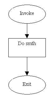
- Consider we want to create our first diagram. It may mirror the work of any program:
- The text of this program can be as follows:
- .PS
- down
- ellipse "Invoke"
- arrow
- box "Do smth"
- arrow
- ellipse "Quit"
- .PE
- To create this piece of code you can use your favorite text editor after that compile it and see if your program produce a desired diagram.
- This so called BATCH approach .Of course it seems not so convenient to do changes and only after recompiling see the change. Another option is to open Diamond-Draw program and do it there. What we see once opening Diamond-Draw?
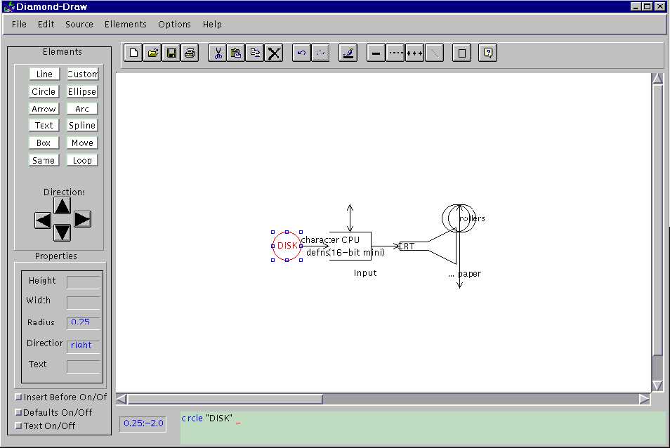
- Main window looks as follows:
- On the left panel there is Pic token bar directions buttons ,properties bar and some checkboxes . In our first example we will use first two to perform Diagram 1 So the first keyword is down. This is one of the four basic directions in which element can be drawn (related to last element).
- We can set this direction (down) by clicking Down direction button.
- After that we want to draw ellipse with <Invoke> text inside. You paid attention that our box has internal text (further we called it associated text) .For bounded elements such as box, circle or ellipse you can set if program asks you for associated text automatically or not.
- This option can be set using Text On/Off text checkbox which can be found at left panel.We can use it and as we will see later this will economize some time.Nevertheless Text Off is default.
- Assume we choose this option. Now clicking Ellipse button cause dialog for
- associated text to appear. There we will type <Invoke> and after clicking OK or pressing Enter ( in all dialogs pressing Enter is equivalent to clicking OK button ) ellipse with text Invoke will appear on the screen. Element is signed by color border which means Current element. More about it you can read in the next chapter.
- Now we can continue with arrow just clicking the Arrow button. It will be drawn down related to the ellipse since direction we set entirely takes effect until other direction chosen. Since the rest actions to complete the diagram are same to already done we leave to reader complete this diagram.
- After diagram is done we can compare text generated by program to source code above.To do that open View menu and choose View source option. Separate window with already familiar text will be opened.
- During the work you of course paid attention that for every drawn element Properties window on pic token toolbar has description of current element attributes. There are so called Default attributes . In future we will see how they can be modifyed or added.
- The other thing that you of course noticed is that mouse location on the screen always can be found in small window near the left bar. Further we will use name Mouse location window for that.
- May be you want to save your first example ? You can do it clicking File menu and then choosing Save As option. Save dialog ( and all file dialogs are the standard ones).
- In the next chapters we will see how to build more complicated pictures so the next example may be helpful.
|
|
 |
|---|
- 2.Introducing edit toolbar and element properties
- The next example will introduce how to use the Edit toolbar and learn how to modify element properties.
- Edit toolbar has all standard file and edit options performed by clicking appropriate icon.
- File options available: New, Open, Save, and Print.
- Edit options available Cut, Copy , Paste , Delete , Undo and Redo
- Special options
- Lets modify a little our first diagram:
- Click on arrow to make it current. Its time to clarify what current element is. You should keep in mind that program always defines current element (even when you open new file current element is default insertion position of first token).
- By definition: Current is the element inserted or modified last.
- Insertion of new element will be done after Current in specified direction as you already saw. All element manipulation via Edit toolbar, Edit menu or mouse are related to current element if not specified otherwise .
- Now we can delete an arrow clicking Delete button at Edit toolbar. What element will be current now? Yes, previously modified (in our case previously drawn) a Box.
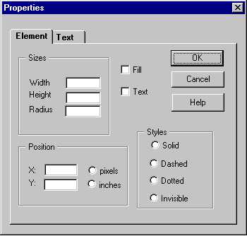
- Then lets modify text in the box . Clicking the right mouse button causes menu to appear. Further we call this menu Current element menu. Current element menu has all basic editing functions such as cut , copy , paste , delete .Also some specific options Properties ( we use it now ) ,Attach label ,and To, At drawing option. So to modify text we choose Properties option. A properties dialog will appear:
- To modify a text we use text page in it . Text page contains all information about text associated to the element. For our box dialog specifies text <do smth> . Other text options will be explained later. Now remove old text and insert desired one. After Enter or OK button is clicked entire picture is changed. Further we do some already familiar operations:
- Specify left direction at left panel
- Clicking arrow button
- Clicking circle button ( when with/without checkbox is checked)
- Insert text Print in a dialog
- Changing direction to down
- Clicking line button
- Changing direction to right
- Clicking arrow button
- What we've got? Of course, not a desired diagram. What happened? All pic tokens has as mentioned some default attributes some of them are height and width. A default line width is 0.5 inch while we need it 0.75 inch to reach the de sired point on the ellipse big diameter. The same argument keeps for arrow also. To change specified element sizes we use already mentioned current element menu and Properties dialog.
- Don't forget to select the line before modifying its attributes. Choose Element page in the dialog. To modify appropriate fields choose it by mouse or pressing the Tab key. Replace line height to 0.75. Doing that we get desired line. F or arrow we need to change its size and location. It can be done using the same dialog for the arrow.
- Location changes in dialog location field. Choose inch representation and add 0.25 inch to Y location. Finally we've got diagram 2.

First of all we delete second arrow (from middle box to last ellipse).
Remark: Inches and pixels radoibuttons are non-relavant ...
- 3. Some direct mouse manipulations
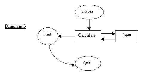
- Consider we want to improve previous diagram in next way. The program transition state has also read input state. It can be as follows: program asks for input and after user specifies the input program makes calculations and prints results as earlier.
- Also we can improve our diagram replacing lines by arc. Now we have some approaches to do that. In general we almost always have at least two ways : using program interface or just typing in text window.
- In this case well explain how to use the interface to achieve our goal. First lets concentrate on<Input> box part. We have two ways to do it using interface.
- We can specify At position for arrow and draw it from that position then draw box and finally specify At position for second arrow and draw it.
- We can draw arrow from calculate box then move it by mouse to desired location then draw box input and repeat with second arrow the same operation.
- Suppose you want to use first alternative .Let us clarify the meanings of At, To options in current element menu.
- At option is used to specify point on element border from it next element be drawn. This mode of operation allows to specify point only on current element border.You'll see the point slider which moves only on element border
- To option is used to specify end point of line/arrow/arc and draw it.
- However we will use At button from the Pic token toolbar to show more interface options . It does almost the same thing but gives a posibillity to specify every point on the screen to be At location point for next insertion. For inserting standalone element it's clear that only this option of interface gives you desired effect (excluding text window of course). After At button clicked user specifies At point using mouse. The sign you are working in At , From-To mode is a different cursor looks like + .
- Then choose left direction and click on arrow. Seems difficult? We can suggest you another alternative.
- Select <calculate> box to set it current then choose left direction and draw arrow. We can move it using mouse only. Click on arrow and without release left mouse button move it to needed position. This is so-called drag'n' drop mode .By mouse you can move element/s and change their size.
- Also you should notice that all elements are standalone and changing position one of them doesnt cause others to change. In case you want to change position of others affected by previous change you should use group move introduced further.
- We suppose you will like the second way more but sometimes you can specify position-using mouse and the first alternative become a useful one.You can add the second arrow in way you like more and the last thing we havent done is replacing line and ar row by an arc. This as you guess can also be done or by mouse or using current element menu and properties dialog. Anyway you must draw a default arc first. Then you can change its position and size by mouse. The only thing you cant do without properties dialog is specifying arrowhead to arc.
- Another thing, which we not faced, is arc curvative direction:
- It is because of default arc curvative direction is anticlockwise. It can also be changed using element Properties dialog. In the next example we introduce some group manipulation, which also can be more useful and quick than every group element manipulation.
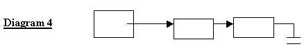
- 4.Direct Mouse manipulations with group of elements
- Consider the next example:
- We have a diagram that shows linked list and suppose we need to do diagram for a hash table. What can be done to make our work more efficient? Program allows you to make manipulations with group of elements. Group selection done by mouse. Click left mouse button and without release it pick out rectangle containing desired group of elements. Actions you can take with group are Copy, Cut, Paste, Move and Delete. To do a hash we need to copy the list and paste it to another place.
- Edit toolbar Copy button and then Paste button may do copying.
- You should specify direction of copy as usual, this means where copy of group will appear. In our example we will choose down direction when the first box is marked as current. New copy will appear exactly after old list in this direction. In o ur example we want the old group and the new one to be close one to other so we will remain the new copy as she. If you need the new group to be at another location you can move it here.

- 5. Using text window
- If you are familiar with Pic language and prefer writing code to mouse manipulation you should use Text window for creating your picture. You have two Text windows:
- One small text window at the bottom of the main window - here you have only one line for inserting code
- Second is just opened text editor invoked by clicking on Source Edit option in the Source popup menu.

- 6. Advanced text manipulations and line styles .
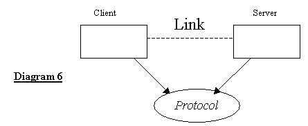
- Suppose we want to create the next diagram. Besides of unusual sizes we see here different font styles. Also well talk a little about text adjustment and everything you might faced with working with text.
- We leave you to create initial diagram with protocol text in ellipse. Lets begin with client server text adjustments. It as mentioned earlier also associated text is an optional element attribute. Associated text can be modified in properties dialog. In the dialog choose Text page and enter <client> <server> appropriately to the boxes. Then choose the Above radiobutton to specify that text will be placed above the box. In the same way we adjust <link> text to line, but the text will be just Link and not a desired Link .As you guess should change a font size for this string. Use Font size combo list at Edit toolbar. In our case the font size is 16, but this is unimportant detail. And finally we change size for <protocol> string and font style also using Edit toolbar.
- Now a little about style option. All element we have drawn up to now used solid line style but it can be changed. Style can be specified as global for all drawing elements or only for current. (This is new option,that is not supported by PIC) In our example we made line Link dashed. Think a little where we change it? Of course using current element menu and element Properties menu. There we have styles settings: solid, dashed, dotted and invisible.
- To modify style globally we must use Edit toolbar.
- 7. More
- To read about specific options you should use a full manual. Here we provide some useful hints which save your time. First of all the manual you have just read can be found in program itself. To read more about other things you can, using Help menu and full manual divided by different contexts into parts.
- Finally we say that in order to use all program power you should learn how to work in text window. This of course forces you to learn PIC language itself a little. Doing some things using a text window allows to save more time but need more intelli gent steps. What are you like more depends on you only.
Glossary
The modes of operationsFirst of all we must to do some assumption:
- Click on smth. means click by left mouse button on smth.
- Choose smth means the same.
- In the each dialogue window the OK button serves for performing the operation while the Cancel button discard the changes made in the dialogue and cancels the operation.
- In each dialogue window the Enter key is equivalent to pressing button while Tab key serves for passing to the next parameter of the dialogue.
- In the Options pop-up menu when the 'V' sign is shown near the option it is ON otherwise the option is OFF.
- Current picture means the picture currently shown in the main window.
- In our program clipboard is simply Pic file.
- Current element is always defined. If no element is selected the last placed element is current.
- To open new picture:
- From File pop up menu choose New or just click to the New button on the toolbar.
- The main window will be clear and you can start to draw the new picture now.
- To save the picture shown on the screen with specified file name:
- From File pop up menu choose Save As. In the appeared dialogue window specify the disk, directory and file name where you want the picture to be stored. Click the OK button to save the picture or Cancel button to discard the action.
- To save the picture with previously specified file name:
- From File pop up menu choose Save or just click the Save button on the toolbar. If the file name not specified you will be asked to specify it by the Save As dialogue window.
- To open the previously saved picture:
- From File pop up menu choose Open or just click the Open button on the toolbar. In the appeared dialogue window specify the disk, directory and file in it. You should also indicate the type of files you want to be shown, that is extension. As a rule the Pic files has the .pic extension.
- To close the current picture:
- From File menu choose Close. If you have done some changes after the last saving the you will be suggested to save the picture before closing.
- To preview the current picture before printing:
- From File pop up menu choose Print Preview. You will see the picture as it will be printed.
- To print the current picture:
- From File pop up menu choose Print or just click the Print button on the toolbar. In the appeared dialogue window choose the printer name and number of copies to be printed.
- To append the file ( containing picture ) to the end of current picture:
- From File pop up menu choose Append File. In the appeared dialogue window specify the disk, directory and file in it. You should also indicate the type of files you want to be shown, that is extension. As a rule the Pic files have the .pic extension. The chosen Pic file will be appended to the current file and the resulting picture will be shown on the screen.
- To insert the file ( containing picture ) into the current picture:
- Select the current element after which you want to insert another file. From File pop up menu choose Insert File. In the appeared dialogue window specify the disk, directory and file in it. You should also indicate the type of files you want to be shown, that is extension. As a rule the Pic files have the .pic extension. The chosen Pic file will be inserted into the current file after current element and the resulting picture will be shown on the screen.
- To exit the program:
- From File pop up menu choose Exit.
- To change the scale range:
- From Options pop up menu choose Scale. In the appeared dialogue window specify the desired scale range and units of measure .
- To change the defaults for figure parameters:
- From Options pop up menu choose Set defaults. In the appeared dialogue window specify the default values for figure parameters: width of a box , height of a box , width of an ellipse , height of an ellipse , radius of a circle , radius of an arc , horizontal line length , vertical line length , horizontal move length , vertical move length.
- To show or hide the grid:
- System has a default grid 0.05x0.05 inch and uses its corners as possible location for element borders.Grid is relative and not influenced upon picture centering related to the elements. Changing grid settings you specify new possible multiples for element size changing.By default minimal element size changing is 0.05 inch.
- There is a Show Grid option in the Options pop up menu. When the grid is shown on the screen this option is marked by the V sign. Choosing this option you show or hide the grid.
- click Grid button on toolbar. Choosing this option you can show or hide the grid
- To change grid settings:
- Choose Grid settings option from Options pull down menu. In appeared dialog specify needed grid sizes or set differnt grid style
Assumptions: Most of these operations are duplicated at the pop up menu appeared when the right mouse button is pressed. They also present at Edit toolbar.
- To select the single element:
- Just click on it.
- To select the group of elements:
- Click the left mouse button and drag the mouse without releasing the button. When you release the button the rectangle is specified. All the elements within this rectangle become selected.
- To select all elements on the current picture:
- From Edit pop up menu choose Select All. All elements will be marked by the dashed frame. Now you can copy them to the clipboard or cut them.
- To clear the picture:
- From Edit pop up menu choose Clear. All the element of the current picture will be deleted. The same result is achieved when you are selecting all the element and then cutting them.
- To move the selected element/s:
- You can drag element by mouse.Select the element/s and drag it to desired location.
- To cut the selected element/s:
- Select the element/s. From Edit pop up menu choose Cut or just click the Cut button on the toolbar. The selected element/s is cut to the clipboard.
- To copy the selected element/s:
- Select the element/s. From Edit pop up menu choose Copy or just click the Copy button on the toolbar. The selected element/s is copied to the clipboard.
- To paste the element/s from the clipboard:
- From Edit pop up menu choose Paste or just click the Paste button on the toolbar. The clipboards content will be placed after the current element.
- To undo the last element:
- From Edit pop up menu choose Undo. From the nested pop up menu choose Last Element. If the last operations was done on group of elements the previous picture state will be restored.
- To undo the last parameter changing:
- From Edit pop up menu choose Undo. From the nested pop up menu choose Last Parameter.
- To redo the last operation:
- From Edit pop up menu choose Redo or just click the redo button on the toolbar.
- To fill the current element:
- From Edit pop up menu choose Fill. The current element will be filled. This action is only available for the box, circle and ellipse.
- To attach the label to the current element:
- From Edit pop up menu choose Attach Label. In the appeared dialogue window type the text that will be the label to the current element.
- To change the current elements properties:
- From Edit pop up menu choose Properties. In accordance with the current element the appropriate dialogue window will appear. There are three kinds of properties dialogues:
- Properties of box/circle/ellipse.
- Properties of line/spline.
- Properties of arc
- Properties of standalone text.
In the suggested Element page you can change the properties relevant for the current element. Irrelevant properties will be unavailable. For example in the dialogue No.1 the radius field will only be available for the circle while width and height will only be available for box and ellipse. You can modify the position , style , size and the fill attribute of the element.
In the second kind of the Properties window you can specify properties of line , arc or spline. You can specify the To point of the element when the start point is a previous element. If you want the element to be standalone set the Standalone radio button to the ON state and specify the From parameter. You can also change the direction , radius (not for a line) or style (solid , dashed , dotted , invisible) and set the arrowhead.
For the standalone text you can modify the text itself and its position.
- To define the If ... Then ... Else statement:
- From the Built-in pop up menu choose If ... Then ... Else option. In the appeared dialogue window specify the condition and then-else operations. For more information see the Pic language documentation.
- To define the For ... To ... By statement:
- From the Built-in pop up menu choose For ... To ... By option. In the appeared dialogue window specify the loop conditions and the operation. For more information see the Pic language documentation.
- To draw element number of times
- From the Built-in pop up menu choose Loop option.In the appeared dialogue window specify number of copies and after that select element position and direction to draw.Element will be drawn this number oftimes in this direction from this position
- To view the source pic code of the current picture:
- From View pop up menu choose Source View. The separate text window with the pic source code will be opened.
- To edit the source pic code of the current picture:
- From View pop up menu choose Source Edit. The default Text editor is opened with the source code of the current picture.
Assumptions :
All those operations,except Custom function ,may be performed from text window .
There is a Defaults On/Off radio button on the left side of the window. If it is on the new element is drawn with the default parameters otherwise the Properties dialogue window will appear every time you are drawing a new element.
You can attach a text for any Pic element. There is a Text On/Off radio button. If it is ON the Attached text dialogue window will appear every time you are drawing a new element otherwise elements are drawn without text. The text you are typing in this dialogue will be attached to the drawn element.
There is also standalone text which is the pic element and may be placed at any location in the picture.
All the elements can be drawn by the direct typing of pic commands in the text window described below. In this section we describe only the WYSIWYG approach for elements creation.
- To draw a box:
- From Elements pop up menu choose Box or just click the Box button on the left part of the window.
- To draw a circle:
- From Elements pop up menu choose Circle or just click the Circle button on the left part of the window.
- To draw an ellipse:
- From Elements pop up menu choose Ellipse or just click the Ellipse button on the left part of the window.
- To draw a line:
- From Elements pop up menu choose Line or just click the Line button on the left part of the window.
- To draw an arrow:
- From Elements pop up menu choose Arrow or just click the Arrow button on the left part of the window.
- To draw an arc:
- From Elements pop up menu choose Arc or just click the Arc button on the left part of the window.
- To draw a spline:
- From Elements pop up menu choose Spline or just click the Spline button on the left part of the window.
- To draw the standalone text:
- From Elements pop up menu choose Text or click Text button on the left part of the window. The Text dialogue window will appear. Type the text you want to be printed on the picture.
- To draw same element as previous one :
- From Elements pop up menu choose Same or just click the Same button on the left part of the window
- To draw Custom element:
- From Elements pop up menu choose Custom or just click the Custom button on the left part of the window.In appeared dialogue window choose element from standart library of elements.Next dialog allows you to set neseccary parameters for it.
- To change the drawing direction:
- There are four buttons on the left side of the window: Up, Down, Left, Right. Click the appropriate button and all next drawings will be performed in this direction until you change it.
- To change the drawing style locally:
- From the mouse right button pop up menu choose the desired style ( solid, dashed, dotted or invisible ) Current element will be redrawing with this style.
- To change the drawing style globally:
- Click the appropriate button on the left side of the edit toolbar All new elements will be drawn with the new style until youll change it.
- To change the element size:
- Do the desired element current by the left mouse button clicking. Click on the dashed frame marking the element and drag it without releasing the mouse button. If there are some restrictions on the size they are kept during resizing. For example you can change only length for the line while you can change both width and height for the box. When resizing the circle the height and the width stay the same i.e. it remains to be circle.
- To move the element to another place:
- Do the desired element current by the left mouse button clicking. Click on the element center and drag it without releasing the mouse button then drop it at needed place by the mouse button releasing.
- Another way is to choose the Move option from the Edit pop up menu and then move the current element by keyboard arrow keys.
- To change the line or arrow direction:
- Click the right vertex of the line or arrowhead. Drag the point to desired position without releasing the button.
There is one lines in the text window placed at the screen bottom. There you can type the pic command and its result will appear on the picture when it become the valid pic command that is if you type box the box will drawn when the x letter is typed and it will be erased if you erase the x letter because bo is not a valid pic command.
The command typed in the text window is inserted to the pic source file as it was in the direct source pic code editing.
Another feature of this mode is automatic token completion. If you press the End key during the command typing the token is completed automatically if the typed word is a prefix of any valid pic token. If you use UNIX operating system you should be familiar with this feature -- in UNIX it exists for file names.
There is also automatic speller in the text window. Each word that is the valid pic token will be marked by the blue color font.
- To get the general information about the Diamond-Draw system:
- From Help pop up menu choose About.
- To get the tutorial:
- From Help pop up menu choose Tutorial.
- To search the help information by topics:
- From Help pop up menu choose Contents.
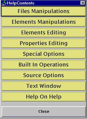
You can get an information about wanted topic just by clicking on it.