| NOTE: If you are replacing an existing adapter with a new adapter, you must re-install the driver. |
Put the Adapter in
the Server
Connect
the UTP Network Cable
Connect the
Fiber Optic Network Cable (Intel PRO/1000 Fiber Adapters Only)
| NOTE: If you are replacing an existing adapter with a new adapter, you must re-install the driver. |
| CAUTION: Turn off and unplug the server before removing the server's cover. Failure to do so could endanger you and may damage the adapter or server. |
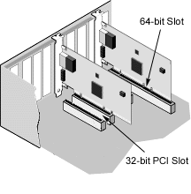
PCI slots are either 32- or 64-bits, and operate at either 33 or 66 MHz. PCI-X slots are backward-compatible with PCI, 32- or 64-bits wide, and operate at 66, 100 or 133 MHz. You should choose the fastest available slot for best performance.
PCI and PCI-X bus theoretical speed designations are shown below:
| 33 MHz | 66 MHz | 100 MHz | 133 MHz | |
| 32-bit | 1x | 2x | 3x | 4x |
| 64-bit | 2x | 4x | 6x | 8x |
| NOTE: All Intel PRO/1000 server adapters utilize a 64-bit PCI 2.2 connector. Therefore you should install these adapters in a 64-bit slot for best performance. If you install the adapter in a 32-bit PCI slot, the end of the edge connector will be exposed. The exposed connector should not touch any part of the motherboard. |

| NOTE: For more information on the PCI bus and installing expansion cards, see the User's Manual that was supplied with your system. |
Insert the twisted pair, RJ-45 network cable as shown below.

Type of cabling to use:
| CAUTION: If using less than 4-pair cabling, you must manually configure the speed and duplex setting of the adapter and the link partner. In addition, with 2- and 3-pair cabling the adapter can only achieve speeds of up to 100Mbps. |
In all cases:
| CAUTION: The fiber optic ports contain a Class 1 laser device. When the ports are disconnected, always cover them with the provided plug. If an abnormal fault occurs, skin or eye damage may result if in close proximity to the exposed ports. |
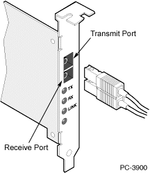
Remove and save the fiber optic connector cover. Insert a fiber optic cable into the ports on the network adapter bracket as shown below.

Most connectors and ports are keyed for proper orientation. If the cable you are using is not keyed, check to be sure the connector is oriented properly (transmit port connected to receive port on the link partner, and vice versa).
Type of cabling to use:
The adapter must be connected to a compatible link partner, such as an IEEE 802.3z-compliant gigabit switch, which is operating at the same laser wavelength as the adapter.
Please read all restrictions and disclaimers.