This chapter provides the following information:
![]() Checking
if Correct Drivers are Loaded
Checking
if Correct Drivers are Loaded
![]() Software
Problems and Solutions
Software
Problems and Solutions
Loopback diagnostic tests are available for testing the adapter hardware under Windows. These tests provide access to the adapter's internal/external diagnostics, where packet information is transmitted across the physical link (for DOS applications, refer to "DOS Diagnostic User's Guide", and for Windows applications refer to "Diagnostics", in the Broadcom Advanced Control Suite section).
The adapter has four LEDs, one for each
port speed option (10 Mbps, 100 Mbps, and 1 Gbps), and one for Activity. The
three port speed LEDs indicate active links, and the Activity LED indicates
data transfer status. Once the driver is loaded and the cables are connected
properly, the appropriate speed LED is lit and the data LED is on if data traffic
is present. Before the port LEDs can provide troubleshooting information, the adapter must
be connected to the network (see "Installing the Hardware"),
and the network drivers for your particular operating system must be installed.
| LED | State | Description |
| 1000 | On | Good Gigabit Ethernet link. |
| Off | No 1000 Mbps link; possible link at different speed, possible bad cable, bad connector, or configuration mismatch. | |
| 100 | On | Good 100 Mbps Fast Ethernet link. |
| Off | No 100 Mbps link; possible link at different speed, possible bad cable, bad connector, or configuration mismatch. | |
| 10 | On | Good 10 Mbps Fast Ethernet link. |
| Off | No 10 Mbps link; possible link at different speed, possible bad cable, bad connector, or configuration mismatch. | |
| ACT | Blinking | Brief bursts of data detected on the port. |
| On | Streams of data detected on the port. | |
| Off | No data detected on the port. |
The adapter has two LEDs, one for each Activity (ACT and LINK). The ACT LED indicates data transfer status. Once the adapter is installed and the cables are connected properly, the speed LED is lit and the ACT LED is on if data traffic is present. The LINK LED indicates the port speed option (10 Mbps, 100 Mbps, and 1000 Mbps) for ports 1 and 2.
Before the port LEDs can provide troubleshooting information, the adapter must be connected to the network (see "Installing the Hardware"), and the network drivers for your particular operating system must be installed.
Table 3. Gigabit Ethernet Port LED Status
for Ports 1 and 2 (5704 only)
| LED | State | Description |
| ACT | Blinking | Brief bursts of data detected on the port. |
| On | Streams of data detected on the port. | |
| Off | No data detected on the port. | |
| LINK | On | Good 10, 1000, and 1000 Mbps Fast Ethernet link. |
| Off | No link; possible link at different speed, possible bad cable, bad connector, or configuration mismatch. |
| WARNING Before opening the cabinet of your system for removing or inserting the adapter, please review all precautions outlined under "Safety Precautions." |
The following checklist provides recommended actions to take to resolve problems installing the Gigabit Ethernet Adapter or running it in your system.
The following section describes how to check if the proper drivers are loaded for Windows, NetWare, and Linux.
The Broadcom Advanced Control Suite, Vital Sign screen allows you to view vital adapter information, network status, and network connectivity. Active adapters are listed.
| NOTE Information for non-Broadcom adapters is less comprehensive than information listed for Broadcom adapters. |
To verify that the driver is loaded properly, type
LOAD B57.LAN FRAME_ETHERNET_II NAME=B57_1_EII
This command automatically verifies if the link is active, and if so displays "Link is up".
From the command line, type config then press Enter. The following status information is displayed:
Broadcom NetXtreme™ Gigabit Ethernet Adapter
Version:
Hardware Setting:
Node Address:
Frame Type:
Board Name:
Lan Protocol: ARP (see note)
LAN Protocol: IP Addr: (see note)
| *NOTE The LAN protocol status appears after assigning an IP address to the adapter (i.e., bind). |
To verify that the bcm5700.o driver is loaded properly, run
lsmod
If
the driver is loaded, a line similar to the one below appears, where <size>
|
Module
|
Size
|
Used by
|
|
BCM5700
|
<size>
|
<n>
|
The following section describes how to run the cable diagnostics from the Broadcom Advanced Control Suite. Refer to "Broadcom Advanced Control Suite," for setups and initialization.
| NOTE This test is designed to work for a 1 gigabit copper link (1000BASE-T) only. |
From the Cable Analysis screen the user can monitor conditions of an Ethernet CAT5 cable connection within a cable plant in an Ethernet network.
| NOTE The network connection will be lost when running these tests. |
The Length sub tab allows you to verify cable length and determine whether your configuration has the appropriate cable, which are calculated by a Return Loss algorithm. This utility allows you to determine whether the problem is with the adapter or in the cable plant.
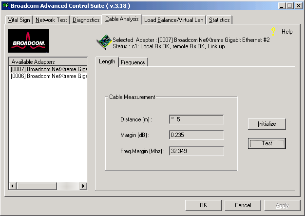
Interface components for the BACS Cable Analysis/Channel Pairs window are described below:
Distance: This field presents the estimated cable length in meters by averaging all four channels using Return Loss algorithms.
Margin: Margin yields the minimum distance between the measured cable pair and the maximum IEEE 802.3ab limits. The unit is in dB.
Each channels frequency response is displayed based on the computation by the cable algorithms. The two graphs represent the values calculated by the Cable Loss and Return Loss algorithms. The vertical axis represents the gain in dB and the horizontal axis represents the operating frequency. The blue graph is the IEEE 802.3ab limit and the red graph is the actual computed values for a particular twisted pair. The minimum Margin and Frequency Margin fields in the Cable Length display are derived from these graphs.
| NOTE Network connection will be lost when running this test. |
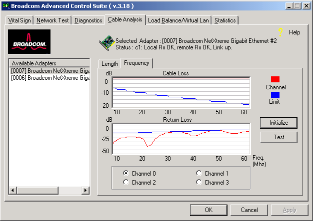
The combination of the cable length and the cable status reveal the state of the cable connection between the local adapter and the far end node (hub/switch/routers). The cable status will display possible problems associated with the cable if the cable is not in working order. In this case, displayed cable length is meaningless since the correct cable length cannot be calculated properly with a broken cable. The status window displays various error messages that diagnose possible problems associated with the cable.
The following section describes how to test network connectivity for Windows 2000, Windows Server 2003, NetWare, and Linux.
| NOTE Ensure that when using forced link speeds, that both the adapter and switch are forced to the same speed OR at least one link partner is configured for Auto-negotiation. |
| NOTE Network connectivity can also be tested using the Network Test feature on the Broadcom Advanced Control Suite. |
Use the ping command to determine if network connectivity is working.
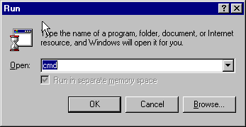
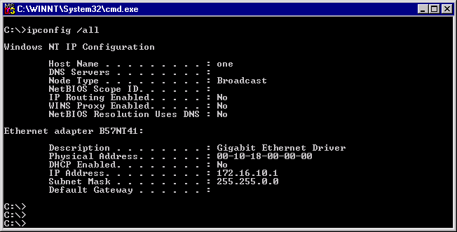
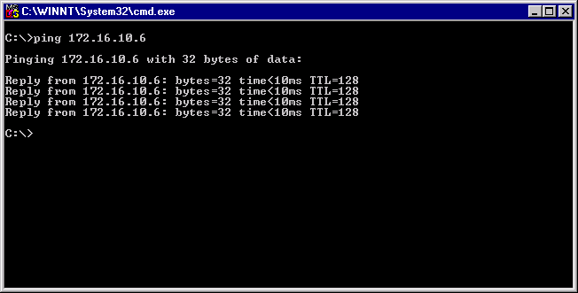
Ping an IP host on the network to verify connection has been established:
From the command line, type ping <IP address>, then press Enter.
This will display the packet send/receive status.
To verify that the Ethernet interface is up and running, run 'ifconfig' to check the status of the Ethernet interface. 'netstat -i' can also be used to check the statistics on the Ethernet interface. Consult manual pages for more information on 'ifconfig' and 'netstat'.
Ping an IP host on the network to verify connection has been established:
From the command line, type ping <IP address>, then press Enter.
This will display the packet send/receive status.
This section provides a list of known software problems and solutions for the operating systems below.
The following table lists know problems and solutions using Windows 2000:
The following table lists known problems and solutions using Linux:
Linux-Basp |
|||
| Problem: When obtaining the IP for a SLB's virtual interface via DHCP, the IP-gets lost under heavy traffic. | Solution: Always set a static IP for all the virtual interfaces in a SLB team. | ||
| Problem: Make install fails on Turbo Linux 7.0 IA64. | Solution: The symbolic link under /lib/modules/<kernel-version>/build
points to an empty directory. To successfully install BASP using `make install`, re-link /lib/modules/<kernel-version>/build to point to /usr/src/<kernel-version>/. |
||
Linux-Core |
|||
| Problem: Compiling the driver fails under SuSE's 7.x. |
Solution: If compiling the driver under SuSE's 7.x distributions and errors are reported, follow the general guidelines below to rebuild the kernel source tree:
where <kernel_version> is the actual kernel version used in the
SuSE distribution.
|
||
| Problem: Zero copy performance is low on Red Hat 7.1. |
Solution: Red
Hat 7.1 loads the ipchains module by default. IPCHAINS is not Example:
|
||
The following table lists known Broadcom Boot Agent problems and solutions:
| Problem: Unable to obtain network settings through DHCP using PXE. |
Solution: For proper operation make sure that the STP (spanning tree protocol) is disabled or portfast mode (for Cisco) is enabled on the port to which the PXE client is connected. For instance, set spantree portfast 4/12 enable. |
||
The following table lists known BASP problems and solutions that apply to all operating systems:
| Problem:
802.3ad team member links disconnect and reconnect continuously. |
Solution: This is a
3rd party issue. It is seen only when configuring an 802.3ad team This does not occur with a Cisco Catalyst 6500. |
||
The following table lists known miscellaneous problems and solutions:
| Problem: When the bus on the system is operating at PCI mode, Broadcom NetXtreme Gigabit Ethernet will perform at PCI mode if it is added by Hot Plug. | Solution: When the system is booted up without any adapter, the bus will operate at the lowest mode which is PCI. This problem can be overcome by rebooting the system. | ||
| Problem: The Broadcom NetXtreme Gigabit Ethernet adapter may not perform at optimal level when it is added by Hot Plug on some system. | Solution: This is because the system BIOS in some system does not set the cache line size and the latency timer, after the adapter is added by Hot Plug. This problem can be overcome by rebooting the system. | ||
| Problem: The Broadcom NetXtreme Gigabit Ethernet adapter can not be seen on the PCI BUS. | Solution: This is because some of the older servers are advertising themselves as PCI-X capable systems. This causes the NetXtreme network adapter to operate in PCI-X mode; therefore; not to be seen by the PCI bus. This problem can be overcome by configuring the firmware to operate in forced pci mode. Refere to b57diag for configuration instructions. | ||